Interactive Mode
The Power Screen
Select <PWR> from the System Screen, as shown in Figure
Line 1 of the Power Screen, as shown in Figure
Lines 2 and 3 display the power supply status as either ON, OFF DUE TO
MANAGEMENT, or FAULT.
Line 4 is used to access information about a specific power supply module by selecting a power supply number.
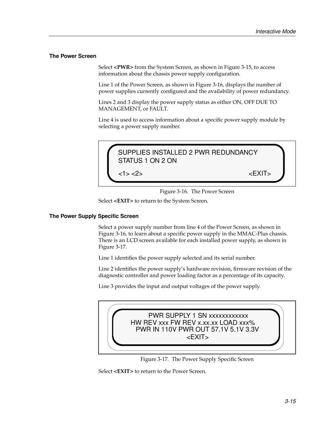
SUPPLIES INSTALLED 2 PWR REDUNDANCY
STATUS 1 ON 2 ON
<1> <2> | <EXIT> |
Figure 3-16. The Power Screen
Select <EXIT> to return to the System Screen.
The Power Supply Specific Screen
Select a power supply number from line 4 of the Power Screen, as shown in Figure
Line 1 identifies the power supply selected and its serial number.
Line 2 identifies the power supply’s hardware revision, firmware revision of the diagnostic controller and power loading factor as a percentage of its capacity.
Line 3 provides the input and output voltages of the power supply.
PWR SUPPLY 1 SN xxxxxxxxxxxx
HW REV xxx FW REV x.xx.xx LOAD xxx%
PWR IN 110V PWR OUT 57.1V 5.1V 3.3V
<EXIT>