The Module Environment Screen
Select <ENV> at the Module Specific Screen, as shown in Figure
Line 1 of the Module Environment Screen, as shown in Figure
Line 2 displays the measured input voltage from the 48 volt system power bus to the module’s
Line 3 displays the module’s current temperature in Fahrenheit and Celsius. The temperature is qualified as either COLD, COOL, NORM (normal), WARM, or HOT based on system parameters.
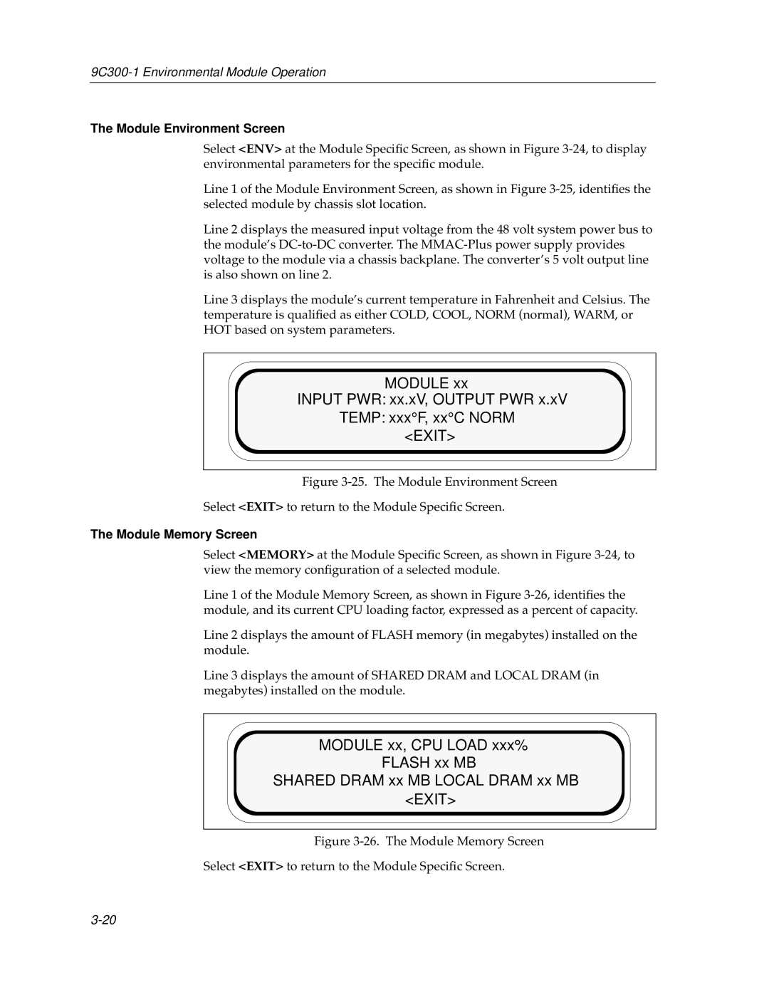
MODULE xx
INPUT PWR: xx.xV, OUTPUT PWR x.xV TEMP: xxx°F, xx°C NORM
<EXIT>
Figure 3-25. The Module Environment Screen
Select <EXIT> to return to the Module Specific Screen.
The Module Memory Screen
Select <MEMORY> at the Module Specific Screen, as shown in Figure
Line 1 of the Module Memory Screen, as shown in Figure
Line 2 displays the amount of FLASH memory (in megabytes) installed on the module.
Line 3 displays the amount of SHARED DRAM and LOCAL DRAM (in megabytes) installed on the module.
MODULE xx, CPU LOAD xxx%
FLASH xx MB
SHARED DRAM xx MB LOCAL DRAM xx MB <EXIT>