Interactive Mode
The Diagnostic Module Selection Screen
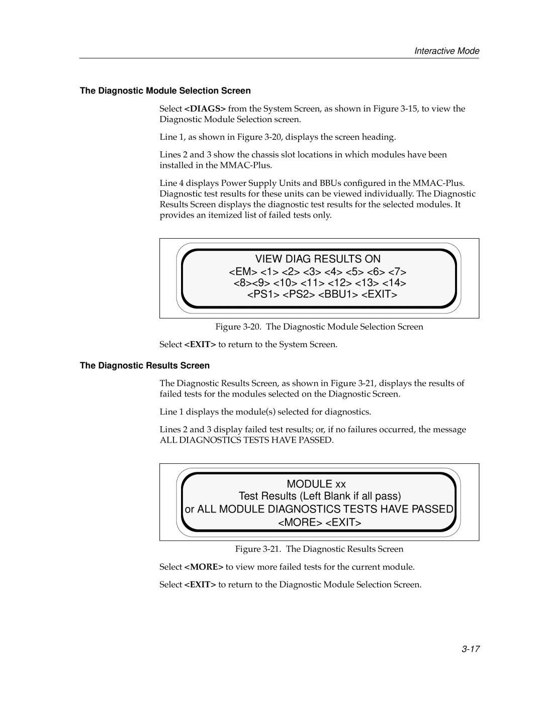
Select <DIAGS> from the System Screen, as shown in Figure
Line 1, as shown in Figure
Lines 2 and 3 show the chassis slot locations in which modules have been installed in the
Line 4 displays Power Supply Units and BBUs configured in the
VIEW DIAG RESULTS ON
<EM> <1> <2> <3> <4> <5> <6> <7> <8><9> <10> <11> <12> <13> <14> <PS1> <PS2> <BBU1> <EXIT>
Figure 3-20. The Diagnostic Module Selection Screen
Select <EXIT> to return to the System Screen.
The Diagnostic Results Screen
The Diagnostic Results Screen, as shown in Figure
Line 1 displays the module(s) selected for diagnostics.
Lines 2 and 3 display failed test results; or, if no failures occurred, the message
ALL DIAGNOSTICS TESTS HAVE PASSED.
MODULE xx
Test Results (Left Blank if all pass)
or ALL MODULE DIAGNOSTICS TESTS HAVE PASSED
