AXIS 2110 User’s Manual | The Unit Connectors | 49 |
Appendix D - The Unit Connectors
This section provides a detailed overview of the two supported product connectors: the Serial Connector and the IO Connector. It also includes connection diagrams for simple door switch and an LED output, as well as a more complete schematic diagram describing how the AXIS 2110 is connected for a typical application.
The Serial Connector
In the absence of a local network connection, the RS232 serial connector provides a physical interface for connecting a modem or computer to the AXIS 2110. This means that the AXIS 2110 can operate as a standalone unit - independent of any computer network. When a local network connection is unavailable at the point of installation, connect your PC to this connector using the supplied Null Modem Cable to initially configure your product.
The Physical Connector
A single 9 pin
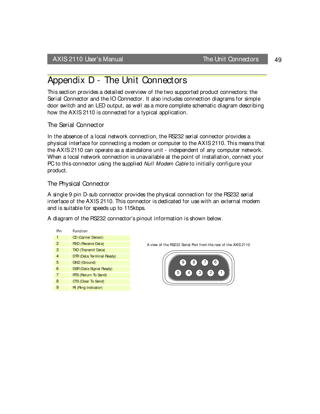
A diagram of the RS232 connector’s pinout information is shown below.
Pin | Function |
1CD (Carrier Detect)
2 | RXD (Receive Data) | A view of the RS232 Serial Port from the rear of the AXIS 2110 | |||||
3 | TXD (Transmit Data) |
|
|
|
|
| |
4 | DTR (Data Terminal Ready) |
|
|
|
|
| |
5 | GND (Ground) |
| 9 | 8 | 7 | 6 | |
6 | DSR (Data Signal Ready) | 5 | 4 | 3 | 2 | 1 | |
7 | RTS (Return To Send) | ||||||
|
|
|
|
| |||
8 | CTS (Clear To Send) |
|
|
|
|
| |
9RI (Ring Indicator)