50 ![]() The Unit ConnectorsAXIS 2110 User’s Manual
The Unit ConnectorsAXIS 2110 User’s Manual
The IO Connector
A
Physical Connector
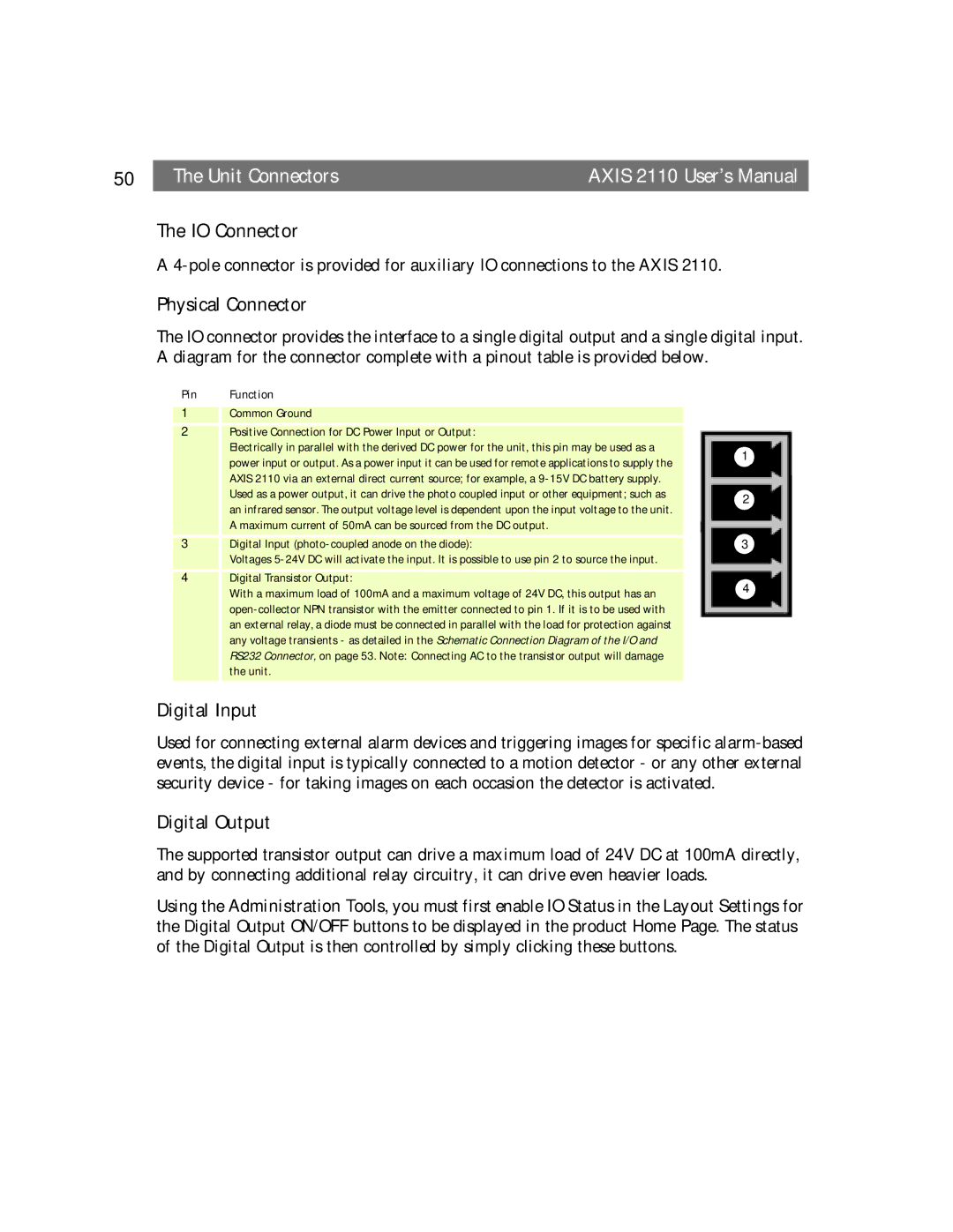
The IO connector provides the interface to a single digital output and a single digital input. A diagram for the connector complete with a pinout table is provided below.
Pin Function
1Common Ground
2Positive Connection for DC Power Input or Output:
Electrically in parallel with the derived DC power for the unit, this pin may be used as a
| power input or output. As a power input it can be used for remote applications to supply the | 1 |
|
| |
| AXIS 2110 via an external direct current source; for example, a |
|
| Used as a power output, it can drive the photo coupled input or other equipment; such as | 2 |
| an infrared sensor. The output voltage level is dependent upon the input voltage to the unit. | |
|
| |
| A maximum current of 50mA can be sourced from the DC output. |
|
3 | Digital Input | 3 |
| Voltages |
|
4Digital Transistor Output:
With a maximum load of 100mA and a maximum voltage of 24V DC, this output has an | 4 |
| |
| |
an external relay, a diode must be connected in parallel with the load for protection against |
|
any voltage transients - as detailed in the Schematic Connection Diagram of the I/O and |
|
RS232 Connector, on page 53. Note: Connecting AC to the transistor output will damage |
|
the unit. |
|
Digital Input
Used for connecting external alarm devices and triggering images for specific
Digital Output
The supported transistor output can drive a maximum load of 24V DC at 100mA directly, and by connecting additional relay circuitry, it can drive even heavier loads.
Using the Administration Tools, you must first enable IO Status in the Layout Settings for the Digital Output ON/OFF buttons to be displayed in the product Home Page. The status of the Digital Output is then controlled by simply clicking these buttons.