CHAPTER 2. TECHNICAL DESCRIPTION
3.2 When a Problem Occurs
[Remedy]
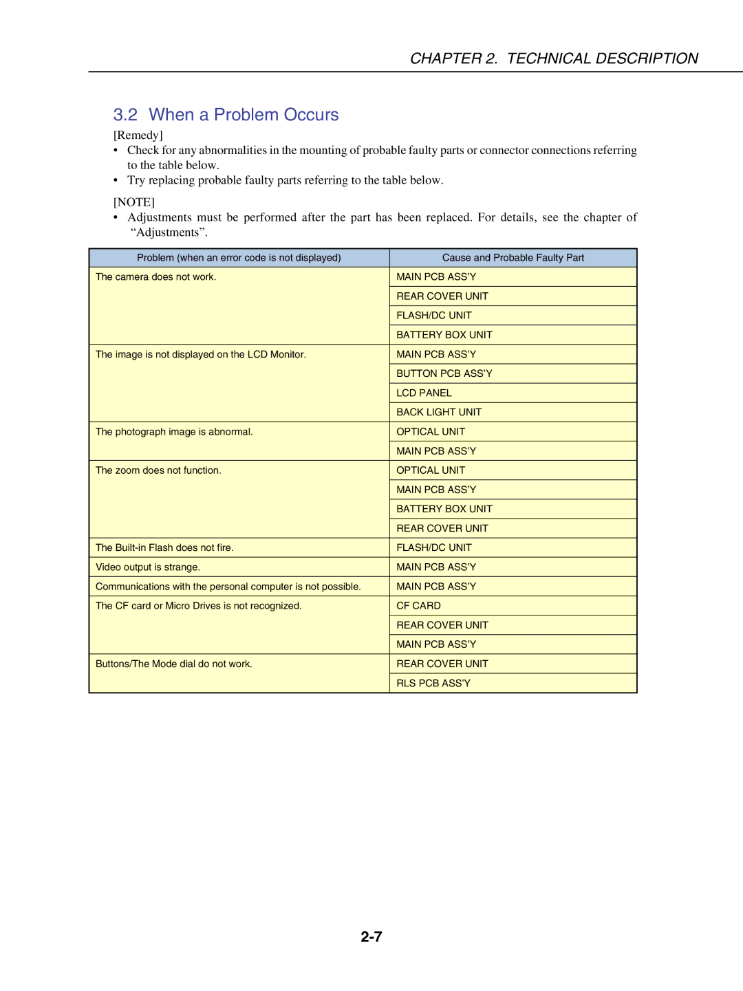
•Check for any abnormalities in the mounting of probable faulty parts or connector connections referring to the table below.
•Try replacing probable faulty parts referring to the table below.
[NOTE]
•Adjustments must be performed after the part has been replaced. For details, see the chapter of “Adjustments”.
Problem (when an error code is not displayed) | Cause and Probable Faulty Part |
The camera does not work. | MAIN PCB ASS’Y |
| REAR COVER UNIT |
| FLASH/DC UNIT |
| BATTERY BOX UNIT |
The image is not displayed on the LCD Monitor. | MAIN PCB ASS’Y |
| BUTTON PCB ASS’Y |
| LCD PANEL |
| BACK LIGHT UNIT |
The photograph image is abnormal. | OPTICAL UNIT |
| MAIN PCB ASS’Y |
The zoom does not function. | OPTICAL UNIT |
| MAIN PCB ASS’Y |
| BATTERY BOX UNIT |
| REAR COVER UNIT |
The | FLASH/DC UNIT |
Video output is strange. | MAIN PCB ASS’Y |
Communications with the personal computer is not possible. | MAIN PCB ASS’Y |
The CF card or Micro Drives is not recognized. | CF CARD |
| REAR COVER UNIT |
| MAIN PCB ASS’Y |
Buttons/The Mode dial do not work. | REAR COVER UNIT |
| RLS PCB ASS’Y |
|
|
