Page
Page
Safety Precautions
Application
General Description Product
Page
Product Concepts
Development Objectives
High grade design / Ultra compact
High Image Quality
Design Concepts
IXY Digital
Features
Settable display times for rec review 2 to 10 seconds
Conceptual diagram of continuous moving image recording
New fast image storage CF card 256 MB
Unwanted scenes can be deleted in movie playback mode
Direct print
Total of 12 image quality modes
VGA-size movies that achieve higher picture quality
Block diagram
PhotoStitch
Main ZoomBrowser EX screen
ZoomBrowser EX 4.0 Win made more ergonomic
Page
File Viewer Utility 1.0 support for Mac OS X at a later date
Apple QuickTime 5.0 Win
PhotoStitch 3.1 for creating precise panoramic pictures
Twain Driver 5.0/WIA Driver 5.0 Win
USB Mounter 1.6 Mac, however only supports OS 9 to OS
Exterior Exterior Photos
6-dimensional diagram
Nomenclature
Screens for Shooting
UI Information
Editing Movies
Setting the Printing Area Trimming
„ Lens
Camera Specifications „ Image sensor CCD
„Optical viewfinder
„White balance
„Focusing
„LCD monitor
„Exposure control
„Flash Built-in
„Shutter and aperture
Varies with shooting modes Shooting interval
„ Shooting specifications
M1/SF
„ Recording specifications Still image
„ Erasing specifications
„Replay specifications
„Interface
„Display specifications
„Others
„Power supplies
„Camera specifications
„ Functions Available in Each Shooting Mode
ZReplay compatibility
CPU
System Requirements
System
Accessories Compatibility
AVC-DC100
System diagram
Additional Guidance
High speed and high precision AF, AE and AWB
Page
Technical Description
Page
Main PCB ASS’Y
Functions of each unit
Outline of Circuits
Power Supply Control
Signal Processing
Picture Processing
When an Error Code is Displayed
Troubleshooting
CF Write
When a Problem Occurs
Page
Repair Instruction
Page
Before Starting the Repair Work
Precaution on Flash High Tension Circuit
List of Supplies
Type D
Flexible Connectors
Procedure
Disassembly/Assembly
CF Cover Spring
Rear Cover UNIT, CF Cover
Front Cover Unit
Front Cover Unit
Shutter Button Unit
Shutter Button Unit
Main PCB ASS’Y
Shield SHEET, Main PCB ASS’Y
Lithium Battery 2ND, Microphone Unit
Lithium Battery 2ND, Microphone Unit
Battery LOCK, Battery Cover
Battery LOCK, Battery Cover
Operation KEY Unit
Operation KEY UNIT, Tripod Socket
LCD PANEL, Back Light Unit
LCD PANEL, Back Light Unit
12 Operation PLATE, Battery BOX UNIT, CF Unit
Operation PLATE, Battery BOX UNIT, CF Unit
Finder Unit Finder Rubber Optical Unit
Optical UNIT, Finder Unit
Barrel
Assembling the Finder Unit
15 Optical Unit
Optical Unit
Flash UNIT, Elect Capacitor
FLASH/DC UNIT, Flash UNIT, Elect Capacitor
Screw List
Replacement Parts and Adjustment Items
Adjustments
Following tools are required for electrical adjustment
Adjustment Tools
Twain Driver Installation
Before Starting Electrical Adjustments
Installing the Adjustment Software
Repair Instruction
Preparation
How to Use the Adjustment Software
Starting up the Adjustment Software
Menu Window
Calibration
Calibration
Camera
Filter FL-W Filter
Place the camera so that the Viewing image
Repair Instruction
CCD Adjustment
Adjustment Procedure
Repair Instruction
Optical Unit Adjustment
Repair Instruction
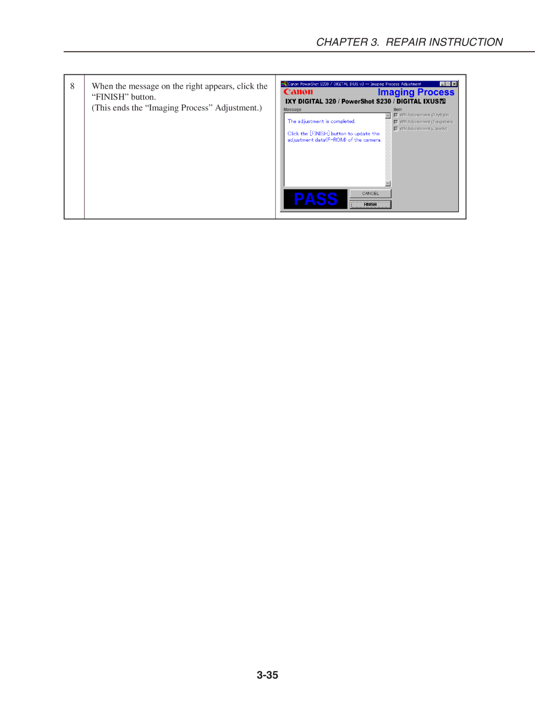
Imaging Process Adjustment
Remove the ND-2 Filter
Repair Instruction
Color Adjustment
Repair Instruction
Pixel Dot Adjustment
Repair Instruction
Flash Adjustment
Repair Instruction
Checking of sound recording/output
Parts Catalog
Page
Casing Parts
R T S L I S T
Internal Parts-1
SHEET, Shield
Internal Parts-2
FLASH/DC Unit
Optical Unit
CAP, BARREL1
CB-2LS/2LSE
C e s s o r i e s
Wrist Strap WS-110
Pg6
Ring
Pg7
Booke PS S230/IXUS For USA, Canada ASIA, Australia
DIA Bond NO.1663G Black
Service Tools
BOND, DIA Bond NO.1663G Black
Diagrams
Page
Interconnection Diagram
Connectors
Overall
Block Diagrams
Main PCB ASS’Y 1/3
Main PCB ASS’Y 1/3
Main PCB ASS’Y 2/3
Main PCB ASS’Y 2/3
Main PCB ASS’Y 3/3
Main PCB ASS’Y 3/3
FLASH/DC Unit
Abbreviation in Block Diagrams
Main PCB ASS’Y
C.B. Diagrams
FLASH/DC Unit Soldering Side FLASH/DC Unit Component Side
Optical Unit
Battery BOX Unit
CF Unit
Operation KEY Unit
How to print out the Zoom/AF Chart
PowerShot S230/DIGITAL Ixus IXY Digital 320 Zoom/AF Chart
Page
PowerShot S230/DIGITAL Ixus v3/IXY Digital 320 Zoom/AF Chart
Dimensions