CHAPTER 3. REPAIR INSTRUCTION
NOTE2 (Assembling)
|
| black gray |
|
Silicon | orange |
| |
|
| ||
DIABOND |
| white | |
| ELECT CAPACITOR | ||
|
| ||
(1633G) |
|
| |
|
|
| |
terminal |
|
| |
terminal |
|
| |
|
|
| |
|
|
| Remove soldering |
|
| l |
|
|
| ||
|
| pink | orange |
|
| ||
|
| FLASH UNIT | Remove |
|
|
| soldering |
|
|
| black |
|
|
| gray |
lwhite
|
| |
| TRIGGRE CAP |
|
h | l | h |
2.0mm |
| |
3.0mm | ||
METAL | METAL | FLASH/DC UNIT |
M1.7 |
| |
M1.4 |
| |
|
|
NOTE1 (Assembling)
Projection part
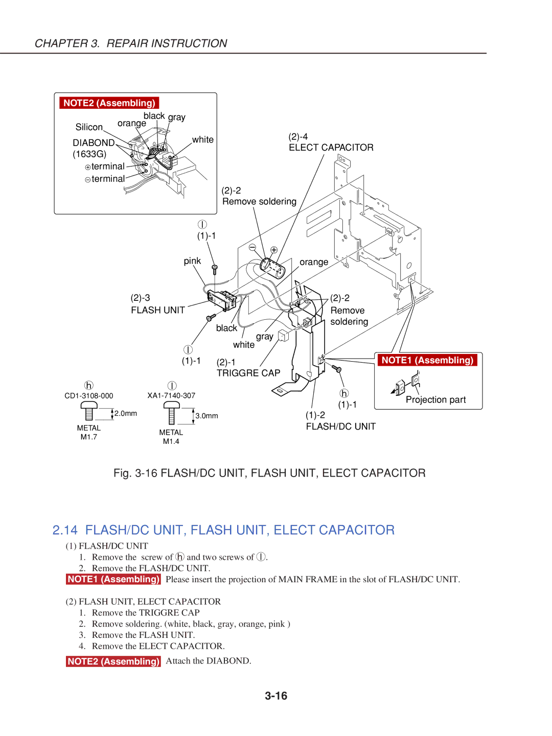
Fig. 3-16 FLASH/DC UNIT, FLASH UNIT, ELECT CAPACITOR
2.14 FLASH/DC UNIT, FLASH UNIT, ELECT CAPACITOR
(1)FLASH/DC UNIT
1.Remove the screw of h and two screws of l.
2.Remove the FLASH/DC UNIT.
NOTE1 (Assembling) Please insert the projection of MAIN FRAME in the slot of FLASH/DC UNIT.
(2)FLASH UNIT, ELECT CAPACITOR
1.Remove the TRIGGRE CAP
2.Remove soldering. (white, black, gray, orange, pink )
3.Remove the FLASH UNIT.
4.Remove the ELECT CAPACITOR.
NOTE2 (Assembling) Attach the DIABOND.