CHAPTER 3. REPAIR INSTRUCTION
NOTE (Assembling)
| |
| |
| |
MAIN PCB ASS'Y |
|
| |
| ||
|
| |
| ||
g |
| |
| g | |
|
|
SHIELD SHEET
3.5mm
METAL
M1.7
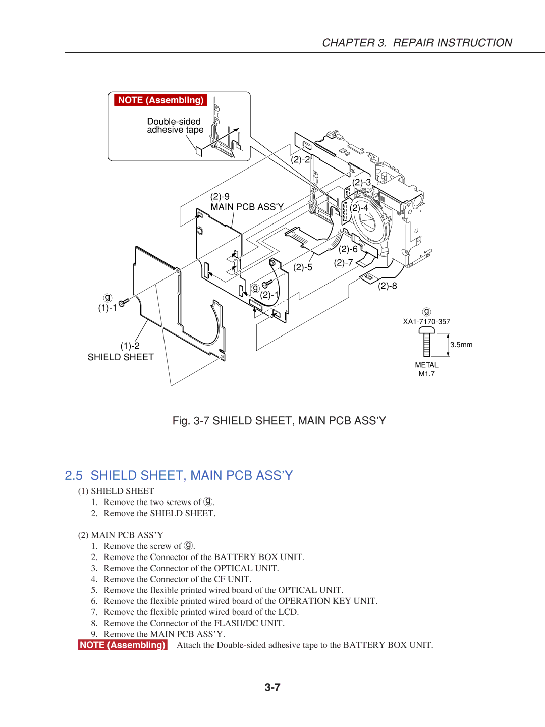
Fig. 3-7 SHIELD SHEET, MAIN PCB ASS’Y
2.5SHIELD SHEET, MAIN PCB ASS’Y
(1)SHIELD SHEET
1.Remove the two screws of g.
2.Remove the SHIELD SHEET.
(2)MAIN PCB ASS’Y
1.Remove the screw of g.
2.Remove the Connector of the BATTERY BOX UNIT.
3.Remove the Connector of the OPTICAL UNIT.
4.Remove the Connector of the CF UNIT.
5.Remove the flexible printed wired board of the OPTICAL UNIT.
6.Remove the flexible printed wired board of the OPERATION KEY UNIT.
7.Remove the flexible printed wired board of the LCD.
8.Remove the Connector of the FLASH/DC UNIT.
9.Remove the MAIN PCB ASS’Y.
NOTE (Assembling) Attach the