Chapter 4 System Startup and Basic System Configuration
Powering On the Router and Observing the Boot Process
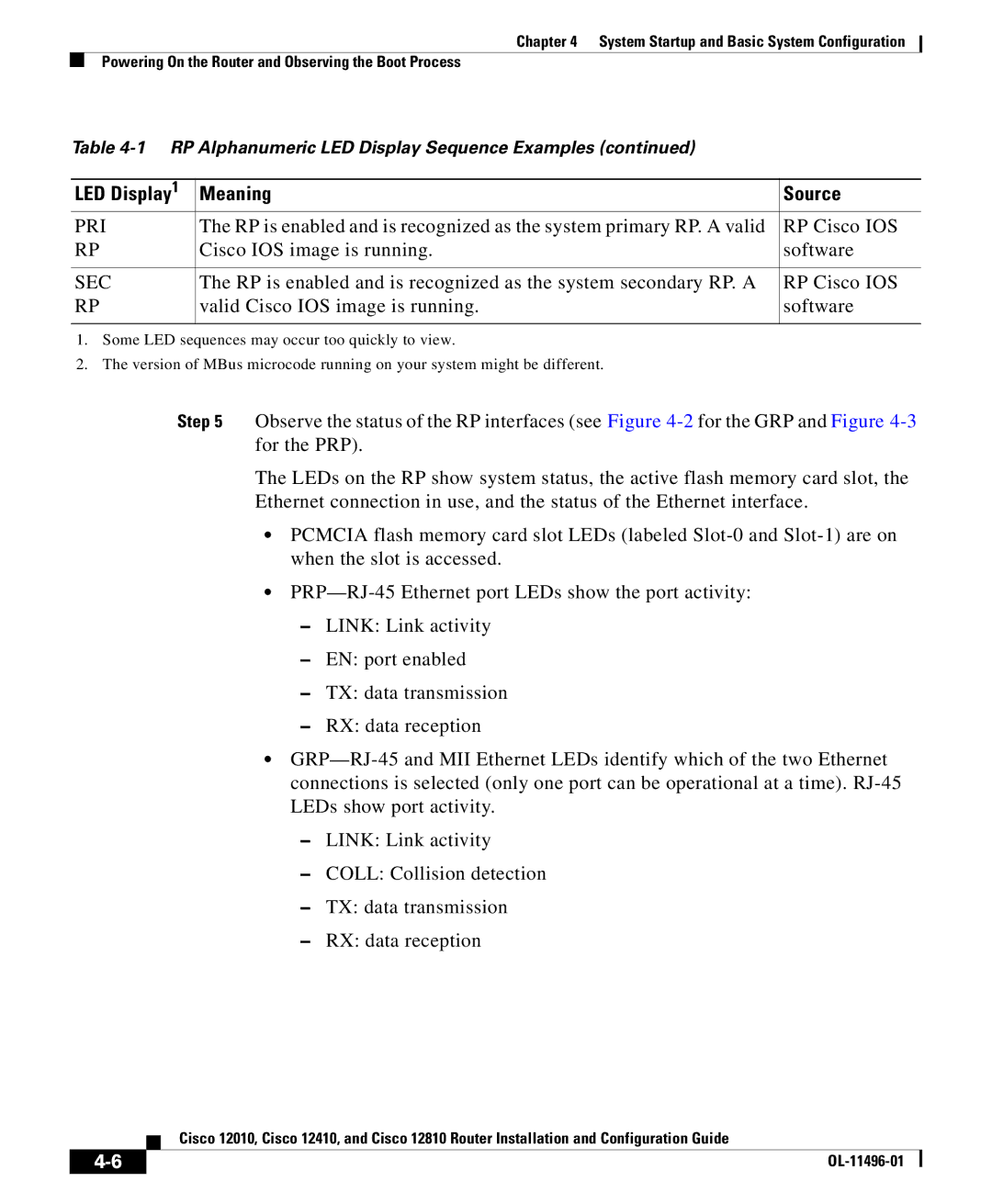
Table
LED Display1 | Meaning | Source |
PRI | The RP is enabled and is recognized as the system primary RP. A valid | RP Cisco IOS |
RP | Cisco IOS image is running. | software |
|
|
|
SEC | The RP is enabled and is recognized as the system secondary RP. A | RP Cisco IOS |
RP | valid Cisco IOS image is running. | software |
|
|
|
1.Some LED sequences may occur too quickly to view.
2.The version of MBus microcode running on your system might be different.
Step 5 Observe the status of the RP interfaces (see Figure
The LEDs on the RP show system status, the active flash memory card slot, the Ethernet connection in use, and the status of the Ethernet interface.
•PCMCIA flash memory card slot LEDs (labeled
•
–LINK: Link activity
–EN: port enabled
–TX: data transmission
–RX: data reception
•
–LINK: Link activity
–COLL: Collision detection
–TX: data transmission
–RX: data reception
| Cisco 12010, Cisco 12410, and Cisco 12810 Router Installation and Configuration Guide |