Chapter 4 System Startup and Basic System Configuration
Powering On the Router and Observing the Boot Process
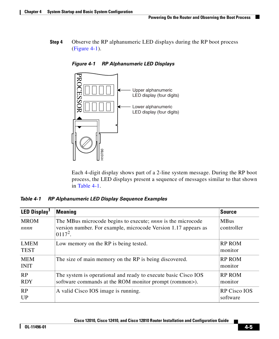
Step 4 Observe the RP alphanumeric LED displays during the RP boot process (Figure
Figure 4-1 RP Alphanumeric LED Displays
PROCESSOR
![]() Upper alphanumeric
Upper alphanumeric
LED display (four digits)
![]() Lower alphanumeric
Lower alphanumeric
LED display (four digits)
H10780 |
Each
Table
| LED Display1 | Meaning | Source | ||
| MROM | The MBus microcode begins to execute; nnnn is the microcode | MBus | ||
| nnnn | version number. For example, microcode Version 1.17 appears as | controller | ||
|
| 01172. |
|
|
|
| LMEM | Low memory on the RP is being tested. | RP ROM | ||
| TEST |
| monitor | ||
|
|
|
| ||
| MEM | The size of main memory on the RP is being discovered. | RP ROM | ||
| INIT |
| monitor | ||
|
|
|
| ||
| RP | The system is operational and ready to execute basic Cisco IOS | RP ROM | ||
| RDY | software commands at the ROM monitor prompt (rommon>). | monitor | ||
|
|
|
| ||
| RP | A valid Cisco IOS image is running. | RP Cisco IOS | ||
| UP |
| software | ||
|
|
|
|
|
|
|
| Cisco 12010, Cisco 12410, and Cisco 12810 Router Installation and Configuration Guide |
|
| |
|
|
| |||
|
|
|
| ||
|
|
|
| ||