Chapter 2 Switch Installation
HP
HP c-Class BladeSystem Enclosure Architecture
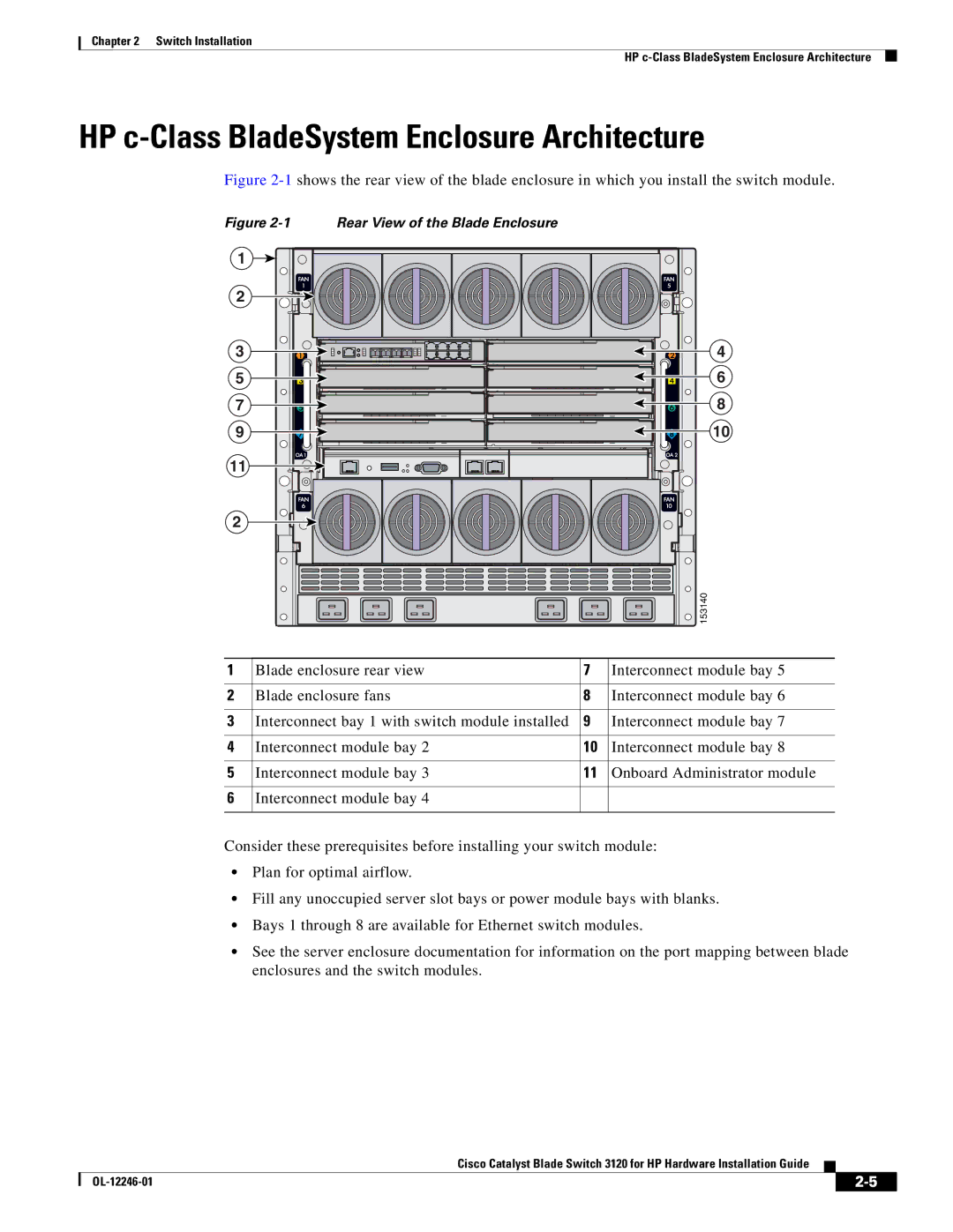
Figure 2-1 shows the rear view of the blade enclosure in which you install the switch module.
Figure 2-1 Rear View of the Blade Enclosure
1 ![]()
2
3
5
7
9
11
2
4
6
8
10
![]()
![]() 153140
153140
1 | Blade enclosure rear view | 7 | Interconnect module bay 5 |
|
|
|
|
2 | Blade enclosure fans | 8 | Interconnect module bay 6 |
|
|
|
|
3 | Interconnect bay 1 with switch module installed | 9 | Interconnect module bay 7 |
|
|
|
|
4 | Interconnect module bay 2 | 10 | Interconnect module bay 8 |
|
|
|
|
5 | Interconnect module bay 3 | 11 | Onboard Administrator module |
|
|
|
|
6 | Interconnect module bay 4 |
|
|
|
|
|
|
Consider these prerequisites before installing your switch module:
•Plan for optimal airflow.
•Fill any unoccupied server slot bays or power module bays with blanks.
•Bays 1 through 8 are available for Ethernet switch modules.
•See the server enclosure documentation for information on the port mapping between blade enclosures and the switch modules.
Cisco Catalyst Blade Switch 3120 for HP Hardware Installation Guide
|
| ||
|
|