Chapter 2 Switch Installation
Installing the Switch Module in the Blade Enclosure
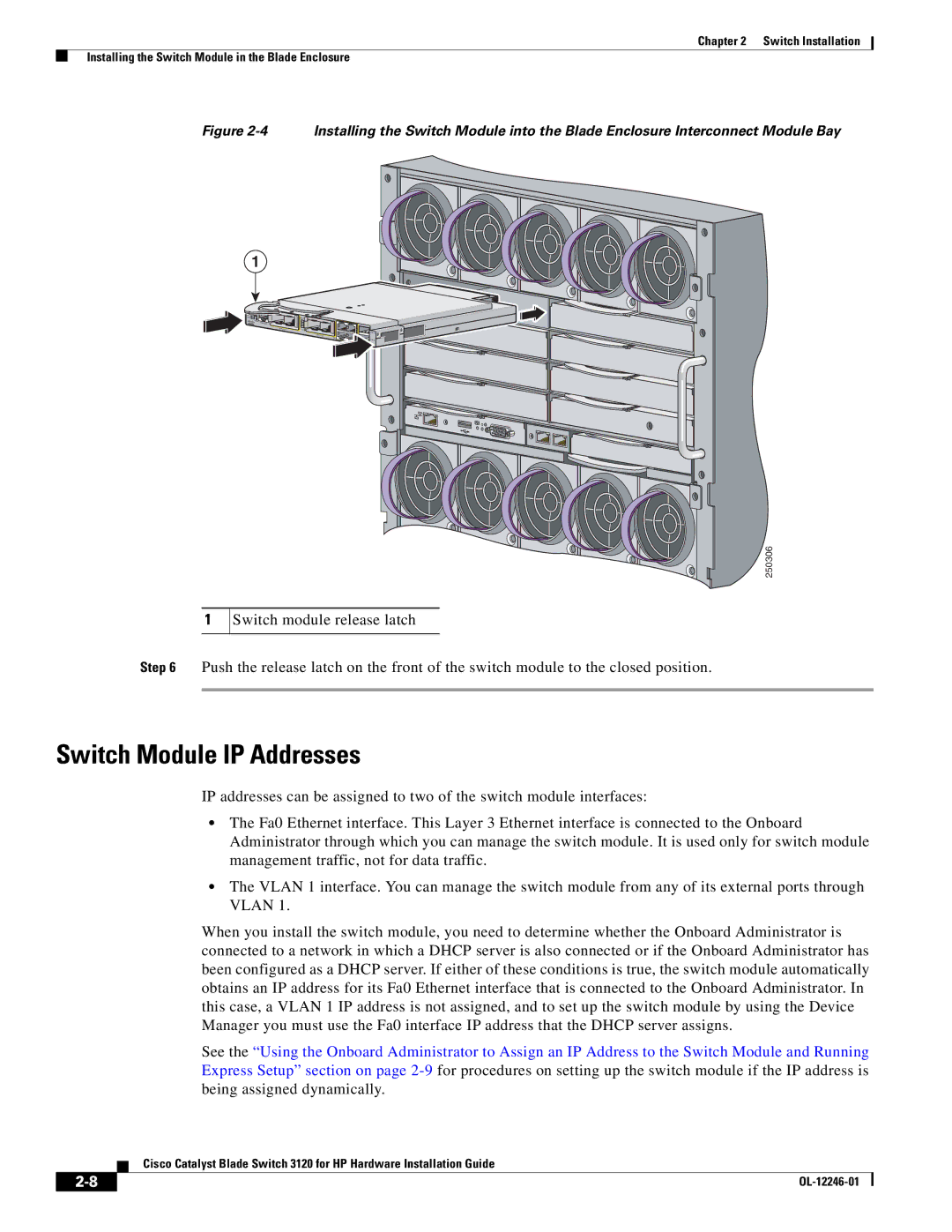
Figure 2-4 Installing the Switch Module into the Blade Enclosure Interconnect Module Bay
1
![]() UID
UID![]()
![]()
![]()
![]()
![]()
![]() 19-20
19-20
MODE
CONSOLE
23x![]()
| STK A |
| SFP |
| 24x |
| STK B |
|
1
250306
Switch module release latch
Step 6 Push the release latch on the front of the switch module to the closed position.
Switch Module IP Addresses
IP addresses can be assigned to two of the switch module interfaces:
•The Fa0 Ethernet interface. This Layer 3 Ethernet interface is connected to the Onboard Administrator through which you can manage the switch module. It is used only for switch module management traffic, not for data traffic.
•The VLAN 1 interface. You can manage the switch module from any of its external ports through VLAN 1.
When you install the switch module, you need to determine whether the Onboard Administrator is connected to a network in which a DHCP server is also connected or if the Onboard Administrator has been configured as a DHCP server. If either of these conditions is true, the switch module automatically obtains an IP address for its Fa0 Ethernet interface that is connected to the Onboard Administrator. In this case, a VLAN 1 IP address is not assigned, and to set up the switch module by using the Device Manager you must use the Fa0 interface IP address that the DHCP server assigns.
See the “Using the Onboard Administrator to Assign an IP Address to the Switch Module and Running Express Setup” section on page
Cisco Catalyst Blade Switch 3120 for HP Hardware Installation Guide
|
| |
|
