Cisco Systems 3120 manual Identifying a Crossover Cable, Console Port Adapter Pinouts, Device

Models: 3120

1 76
Download 76 pages 29.05 Kb
Page 62
Image 62

Appendix B Connector and Cable Specifications

Cable and Adapter Specifications

Identifying a Crossover Cable

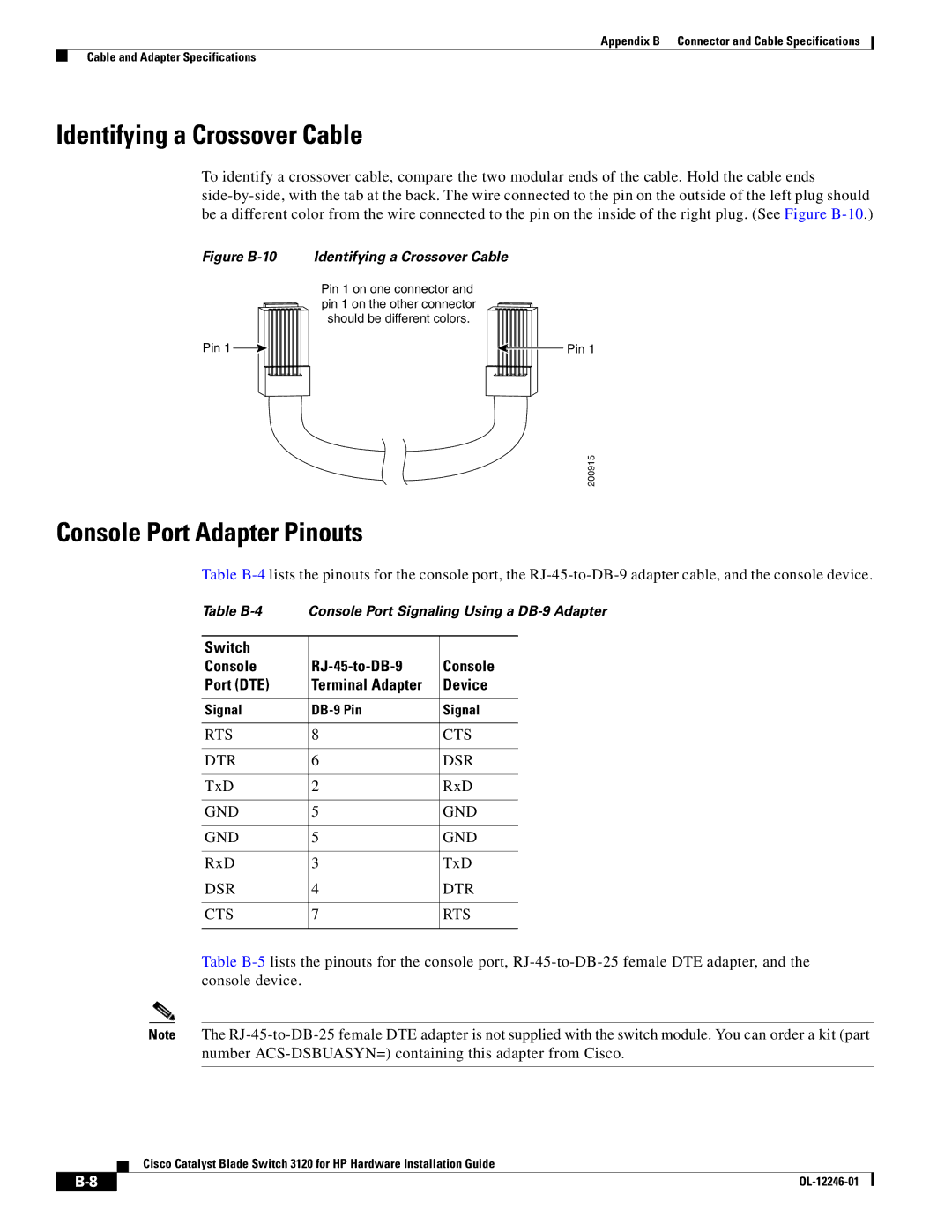
To identify a crossover cable, compare the two modular ends of the cable. Hold the cable ends side-by-side, with the tab at the back. The wire connected to the pin on the outside of the left plug should be a different color from the wire connected to the pin on the inside of the right plug. (See Figure B-10.)

Figure B-10 Identifying a Crossover Cable

Pin 1 on one connector and pin 1 on the other connector should be different colors.

Pin 1


Pin 1


200915

Console Port Adapter Pinouts

Table B-4lists the pinouts for the console port, the RJ-45-to-DB-9 adapter cable, and the console device.

Table B-4 Console Port Signaling Using a DB-9 Adapter

Switch


Console

RJ-45-to-DB-9

Console

Port (DTE)

Terminal Adapter

Device


Signal

DB-9 Pin

Signal


RTS

8

CTS


DTR

6

DSR


TxD

2

RxD


GND

5

GND


GND

5

GND


RxD

3

TxD


DSR

4

DTR


CTS

7

RTS


Table B-5lists the pinouts for the console port, RJ-45-to-DB-25 female DTE adapter, and the console device.

Note The RJ-45-to-DB-25 female DTE adapter is not supplied with the switch module. You can order a kit (part number ACS-DSBUASYN=) containing this adapter from Cisco.

Cisco Catalyst Blade Switch 3120 for HP Hardware Installation Guide


B-8

OL-12246-01


Page 62
Image 62
Cisco Systems 3120 Identifying a Crossover Cable, Console Port Adapter Pinouts, Switch Console RJ-45-to-DB-9 Port DTE