Chapter 2 Switch Installation
Planning and Creating a Switch Stack
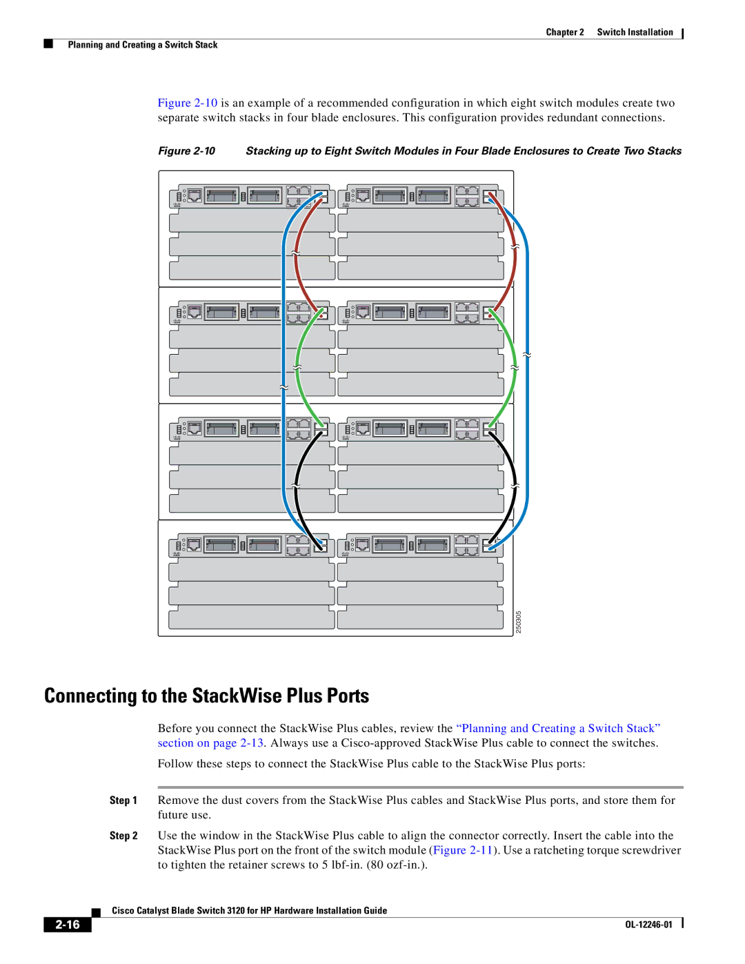
Figure 2-10 is an example of a recommended configuration in which eight switch modules create two separate switch stacks in four blade enclosures. This configuration provides redundant connections.
Figure 2-10 Stacking up to Eight Switch Modules in Four Blade Enclosures to Create Two Stacks
250305
Connecting to the StackWise Plus Ports
Before you connect the StackWise Plus cables, review the “Planning and Creating a Switch Stack” section on page
Follow these steps to connect the StackWise Plus cable to the StackWise Plus ports:
Step 1 Remove the dust covers from the StackWise Plus cables and StackWise Plus ports, and store them for future use.
Step 2 Use the window in the StackWise Plus cable to align the connector correctly. Insert the cable into the StackWise Plus port on the front of the switch module (Figure
| Cisco Catalyst Blade Switch 3120 for HP Hardware Installation Guide |