Chapter 1 Information about the ASA
ASA Chassis Panels
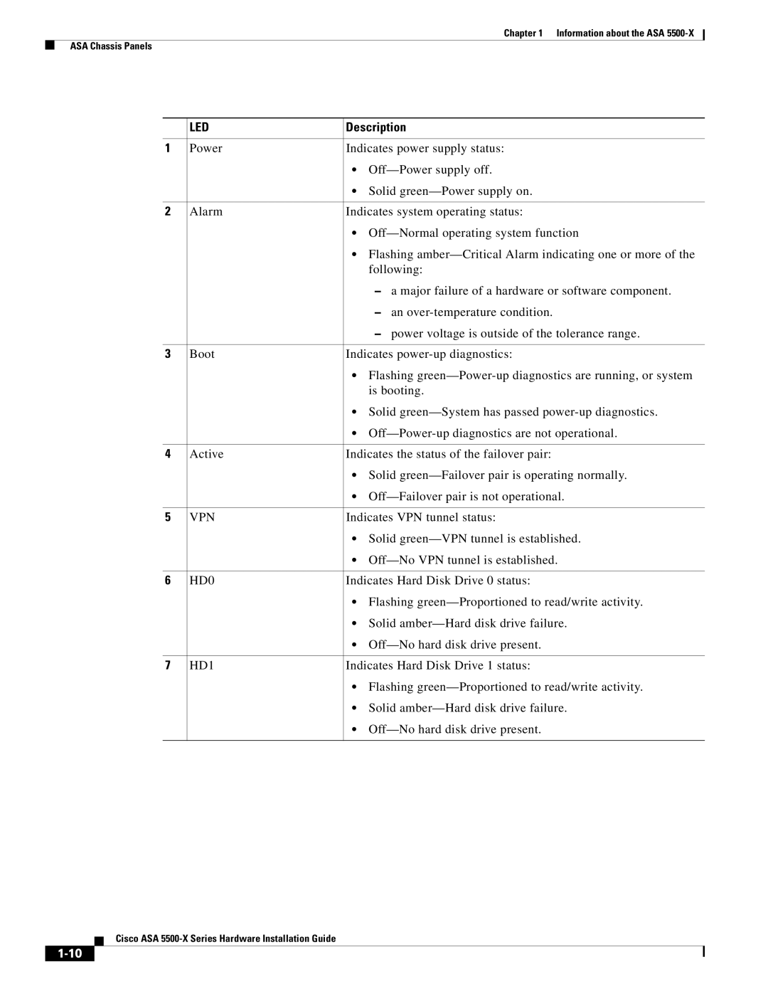
| LED | Description |
|
|
|
1 | Power | Indicates power supply status: |
|
| • |
|
| • Solid |
|
|
|
2 | Alarm | Indicates system operating status: |
|
| • |
|
| • Flashing |
|
| following: |
|
| – a major failure of a hardware or software component. |
|
| – an |
|
| – power voltage is outside of the tolerance range. |
|
|
|
3 | Boot | Indicates |
|
| • Flashing |
|
| is booting. |
|
| • Solid |
|
| • |
|
|
|
4 | Active | Indicates the status of the failover pair: |
|
| • Solid |
|
| • |
|
|
|
5 | VPN | Indicates VPN tunnel status: |
|
| • Solid |
|
| • |
|
|
|
6 | HD0 | Indicates Hard Disk Drive 0 status: |
|
| • Flashing |
|
| • Solid |
|
| • |
|
|
|
7 | HD1 | Indicates Hard Disk Drive 1 status: |
|
| • Flashing |
|
| • Solid |
|
| • |
|
|
|