Chapter 1 Information about the ASA
ASA Chassis Panels
Rear Panel Ports
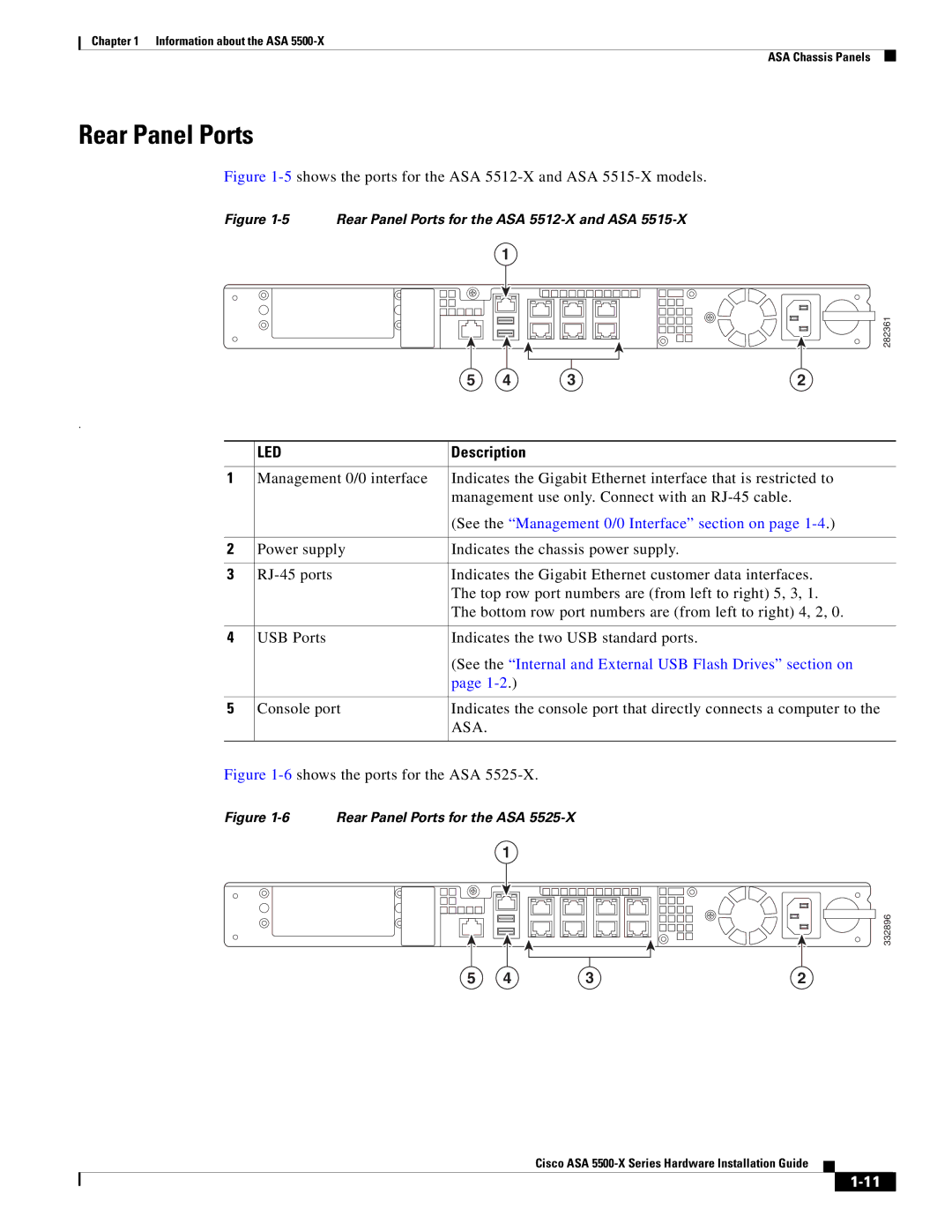
Figure 1-5 shows the ports for the ASA 5512-X and ASA 5515-X models.
Figure | Rear Panel Ports for the ASA |
| ||||
|
|
|
| 1 |
|
|
|
|
|
|
|
| 282361 |
|
|
| 5 | 4 | 3 | 2 |
. |
|
|
|
|
|
|
| LED |
| Description |
|
| |
1 | Management 0/0 interface | Indicates the Gigabit Ethernet interface that is restricted to | ||||
|
|
| management use only. Connect with an |
| ||
|
|
| (See the “Management 0/0 Interface” section on page | |||
2 | Power supply | Indicates the chassis power supply. |
| |||
3 |
| Indicates the Gigabit Ethernet customer data interfaces. | ||||
|
|
| The top row port numbers are (from left to right) 5, 3, 1. | |||
|
|
| The bottom row port numbers are (from left to right) 4, 2, 0. | |||
4 | USB Ports |
| Indicates the two USB standard ports. |
| ||
|
|
| (See the “Internal and External USB Flash Drives” section on | |||
|
|
| page |
|
| |
5 | Console port | Indicates the console port that directly connects a computer to the | ||||
|
|
| ASA. |
|
|
|
Figure 1-6 shows the ports for the ASA 5525-X.
Figure 1-6 Rear Panel Ports for the ASA 5525-X
1
332896
5 | 4 | 3 | 2 |