Cisco Systems, Inc
Cisco ASA 5512-X, ASA 5515-X, ASA 5525-X, ASA 5545-X, and ASA
Cisco ASA 5500-X Series Hardware Installation Guide
Reorient or relocate the receiving antenna
C O N T E N T S
Contents
Where to Find Safety and Warning Information
Installation Warnings
System
Installation Overview
Installing an I/O Card
Installing the SFP Module
Installing and Removing SSDs
Contents
Cisco ASA 5500-X Series Hardware Installation Guide
I N D E
Contents Cisco ASA 5500-X Series Hardware Installation Guide
Contents
Installation Warnings, page
Where to Find Safety and Warning Information, page
Obtaining Documentation and Submitting a Service Request, page
Installation Warnings
Tip Means the following information will help you solve a problem
Power Supply Disconnection Warning, page
More than One Power Supply Warning, page
Power Supply Disconnection Warning
More than One Power Supply Warning
DC Power Connection Warning, page
AC Power Disconnection Warning, page TN Power Warning, page
Installation Instructions Warning
Chassis Warning for Rack-Mounting and Servicing
SELV Circuit Warning
Ground Conductor Warning
DC Power Connection Warning
AC Power Disconnection Warning
TN Power Warning
48 VDC Power System
Where to Find Safety and Warning Information
Safety Cover Requirement
Related Documentation
Grounded Equipment Warning
xiii
Cisco ASA 5500-X Series Hardware Installation Guide
Cisco ASA 5500-X Series Hardware Installation Guide
Management 0/0 Interface, page Alarm LED, page
Power Supply, page Hardware Specifications, page
Information about the ASA
C H A P T E R
Cisco ASA 5500-X Series Chassis Overview
Internal and External USB Flash Drives
Internal USB Drive
Optional External USB Drives
Solid State Drives
Online Insertion and Removal Support
FAT 32 File System
Viewing Flash Memory
Alarm LED
Management 0/0 Interface
For more information, see the “Rear Panel Ports” section on page
ASA 5500-X I/O Cards
SFP Modules
Multimode
ASA Chassis Panels
Front Panel LEDs
Front Panel LEDs, page Rear Panel LEDs, page Rear Panel Ports, page
Considerations” section on page
Alarm
13 12
Description
Considerations” section on page
Figure 1-3 Front Panel LEDs for Cisco ASA 5545-X and ASA
Rear Panel LEDs
Figure 1-4 Rear Panel LEDs for ASA 5500-X Series Chassis
1-10
Description
Rear Panel Ports
See the “Management 0/0 Interface” section on page
See the “Internal and External USB Flash Drives” section on
page
See the “Management 0/0 Interface” section on page
See the “Internal and External USB Flash Drives” section on
1-12
page
Power Supply
5500-X Series Chassis” for more information
1-13
1-14
Power supply indicator
DC power supply positive connection
DC power supply neutral connection
Hardware Specifications
1-15
AC and DC Power Supply Indicator
Hardware Specifications for the Cisco ASA 5500-X series
Console Cable Pinouts
RJ-45 Console Cable
RJ-45 Console Cable, page RJ-45 to DB-9 Console Adapter, page
1-16
1-17
Figure 1-9 shows the RJ 45 cable
RJ-45 to DB-9 Console Adapter
1-18
Cisco ASA 5500-X Series Hardware Installation Guide
Chapter 1 Information about the ASA Console Cable Pinouts
Preparing for Installation
Installation Overview
Safety Recommendations
Installation Overview, page Safety Recommendations, page
Maintaining Safety with Electricity
Maintaining Safety with Electricity, page
Preventing Electrostatic Discharge Damage, page
Working in an ESD Environment, page
Site Environment, page Preventive Site Configuration, page
Power Supply Considerations, page Configuring Equipment Racks, page
General Site Requirements
Preventing Electrostatic Discharge Damage
Preventive Site Configuration
Power Supply Considerations
Site Environment
Appliance Coupler 300 W AC Power Supply
Table 2-1 AC-Input Power Cord Options
Locale
Part Number
Configuring Equipment Racks
Table 2-1 AC-Input Power Cord Options continued
Installing and Connecting the ASA
Connecting Cables, Turning on Power, and Verifying Connectivity, page
Rack Mounting the Chassis
Rack Mounting Guidelines
Rack Mounting the ASA 5512-X, 5515-X, and 5525-X With Brackets
Detailed Steps
Chapter 3 Installing and Connecting the ASA Rack Mounting the Chassis
Cisco ASA 5500-X Series Hardware Installation Guide
BOOT
ALARM
Rack Mounting the Chassis with the Slide Rail Mounting System, page
Rack Mounting the ASA 5500-X Chassis with Slide Rail Mounting System
Detailed Steps
Rack Mounting the Chassis with the Slide Rail Mounting System
See Figure
Prerequisites
Verify the Box Contents
Verify the Rack Type
Tools Required
Detailed Steps
Step 1 Disassemble the slide rail
Round hole insert-Secure it with two of the saved screws
No additional hardware is necessary for the rear adapter
3-10
Round and Square Hole Racks
3-11
Threaded Hole Racks
3-12
Chapter 3 Installing and Connecting the ASA Rack Mounting the Chassis
Cisco ASA 5500-X Series Hardware Installation Guide
330898
Connecting Cables, Turning on Power, and Verifying Connectivity
Guidelines
3-13
Connecting Cables, Turning on Power, and Verifying Connectivity
3-14
Optional I/O Card. If you have a
3-15
For older ASAs, press the power button
3-16
Chapter 3 Installing and Connecting the ASA
Connecting Cables, Turning on Power, and Verifying Connectivity
Cisco ASA 5500-X Series Hardware Installation Guide
Maintenance and Upgrade Procedures for the ASA
Installing an I/O Card, page
Installing and Removing the SFP Modules, page
Removing and Installing the Power Supply, page
Replacing the Chassis Cover
Detailed Steps
Figure 4-1 Removing the Chassis Cover
Installing an I/O Card
Reinstall the chassis on a rack
Reinstall the network interface cables
Power on the chassis
I/O Card holder Power supply
Caution Keep hands clear of all electronics underneath the card cover
1 Index finger placement 2 Thumb placement
Installing an I/O Card in the Cisco ASA 5545-X and 5555-X Chassis
pushing the cover toward the rear of the chassis
Determine the location of the I/O card. See Figure
Detailed Steps
Figure 4-9 Removing the Connector Clamp
Figure 4-10 Removing the Regex Cable Connector
Figure 4-11 Lift the I/O Card Upward to Release it
4-10
Close the green connector clamp
Installing and Removing the SFP Modules
Installing the SFP Module
Installing the SFP Module, page Removing the SFP Module, page
4-11
Removing the SFP Module
4-12
Detailed Steps
Removing and Installing the Power Supply
Removing and Installing the AC Power Supply
Removing and Installing the AC Power Supply, page
Installing the DC Input Power, page
4-14
Step 2 If you are replacing a power supply, follow these steps
Installing the DC Input Power
4-15
PS0PS1
4-16
Fixed fan
4-17
To connect the DC power supply on the appliance, follow these steps
4-18
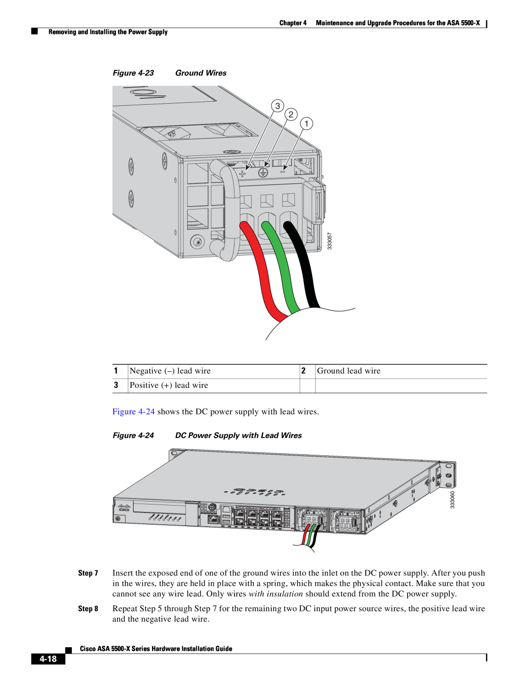
Negative - lead wire
Removing and Installing the DC Power Supply
4-19
Figure 4-25 Complete DC Secure Tie Wrap
4-20
Step 6 If you are replacing a power supply, follow these steps
Installing and Removing the Solid State Drive for the ASA CX SSP
Installation Scenarios
Installation Scenarios, page Installing and Removing SSDs, page
4-21
Installing and Removing SSDs
4-22
Detailed Steps
Figure 4-30 Removing the SSD from the ASA 5512/5515/5525-X
4-23
Figure 4-32 Installing the SSD in the ASA 5512/5515/5525-X
Figure 4-33 Installing the SSD in the ASA 5545-X and ASA
4-24
Chapter 4 Maintenance and Upgrade Procedures for the ASA
Installing and Removing the Solid State Drive for the ASA CX SSP
Cisco ASA 5500-X Series Hardware Installation Guide
Numerics
I N D E
IN-1
IN-2