Chapter 3 Installing and Connecting the ASA
Rack Mounting the Chassis
Detailed Steps
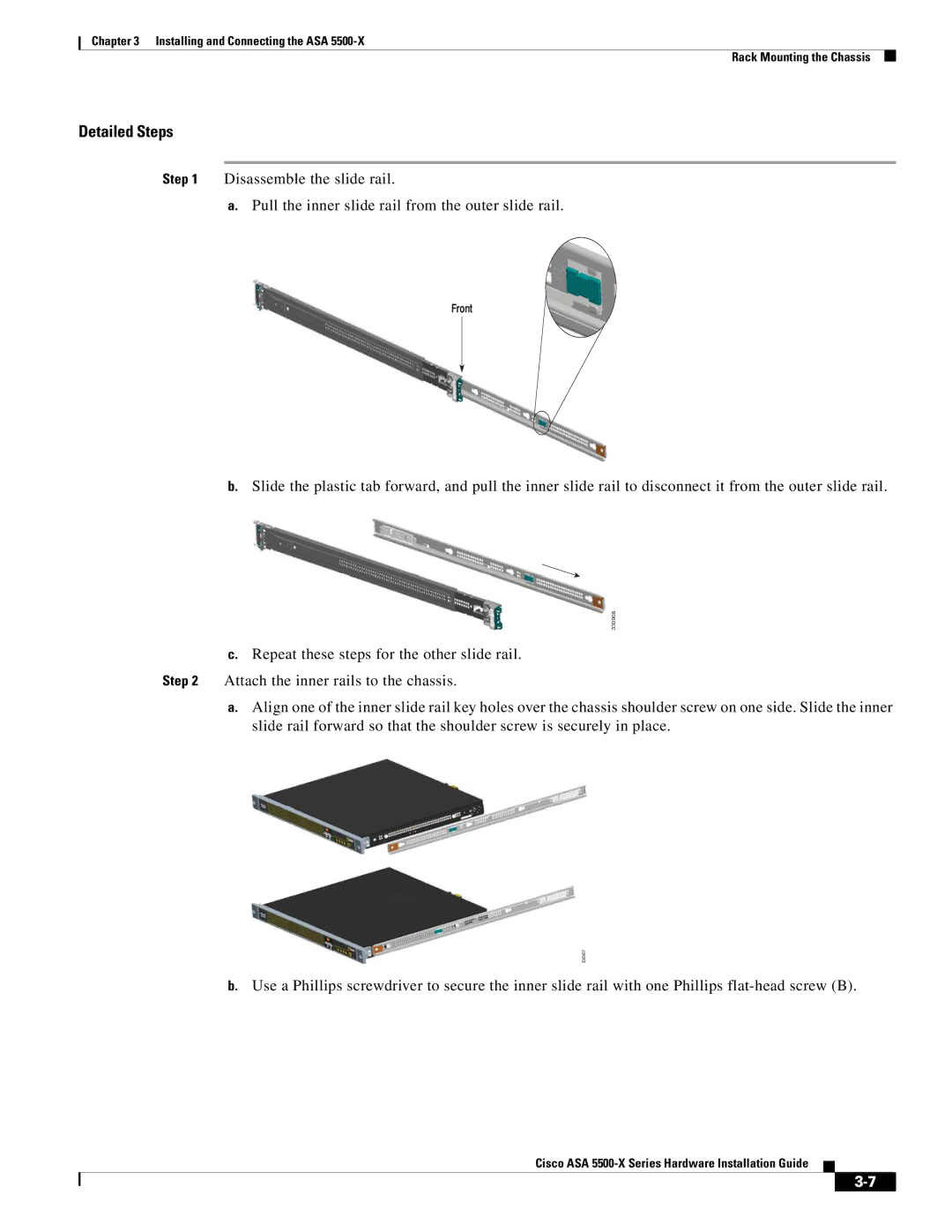
Step 1 Disassemble the slide rail.
a.Pull the inner slide rail from the outer slide rail.
Front
b.Slide the plastic tab forward, and pull the inner slide rail to disconnect it from the outer slide rail.
330908
c.Repeat these steps for the other slide rail.
Step 2 Attach the inner rails to the chassis.
a.Align one of the inner slide rail key holes over the chassis shoulder screw on one side. Slide the inner slide rail forward so that the shoulder screw is securely in place.
330907
b.Use a Phillips screwdriver to secure the inner slide rail with one Phillips