Chapter 1 Information about the ASA
ASA Chassis Panels
| LED | Description |
|
|
|
1 | Management 0/0 interface | Indicates the Gigabit Ethernet interface that is restricted to |
|
| management use only. Connect with an |
|
| (See the “Management 0/0 Interface” section on page |
|
|
|
2 | Power supply | Indicates the chassis power supply. |
|
|
|
3 | Indicates the Gigabit Ethernet customer data interfaces. | |
|
| The top row port numbers are (from left to right) 7, 5, 3, 1. |
|
| The bottom row port numbers are (from left to right) 6, 4, 2, 0. |
|
|
|
4 | USB Ports | Indicates the two USB standard ports. |
|
| (See the “Internal and External USB Flash Drives” section on |
|
| page |
|
|
|
5 | Console port | Indicates the console port that directly connects a computer to the |
|
| ASA. |
|
|
|
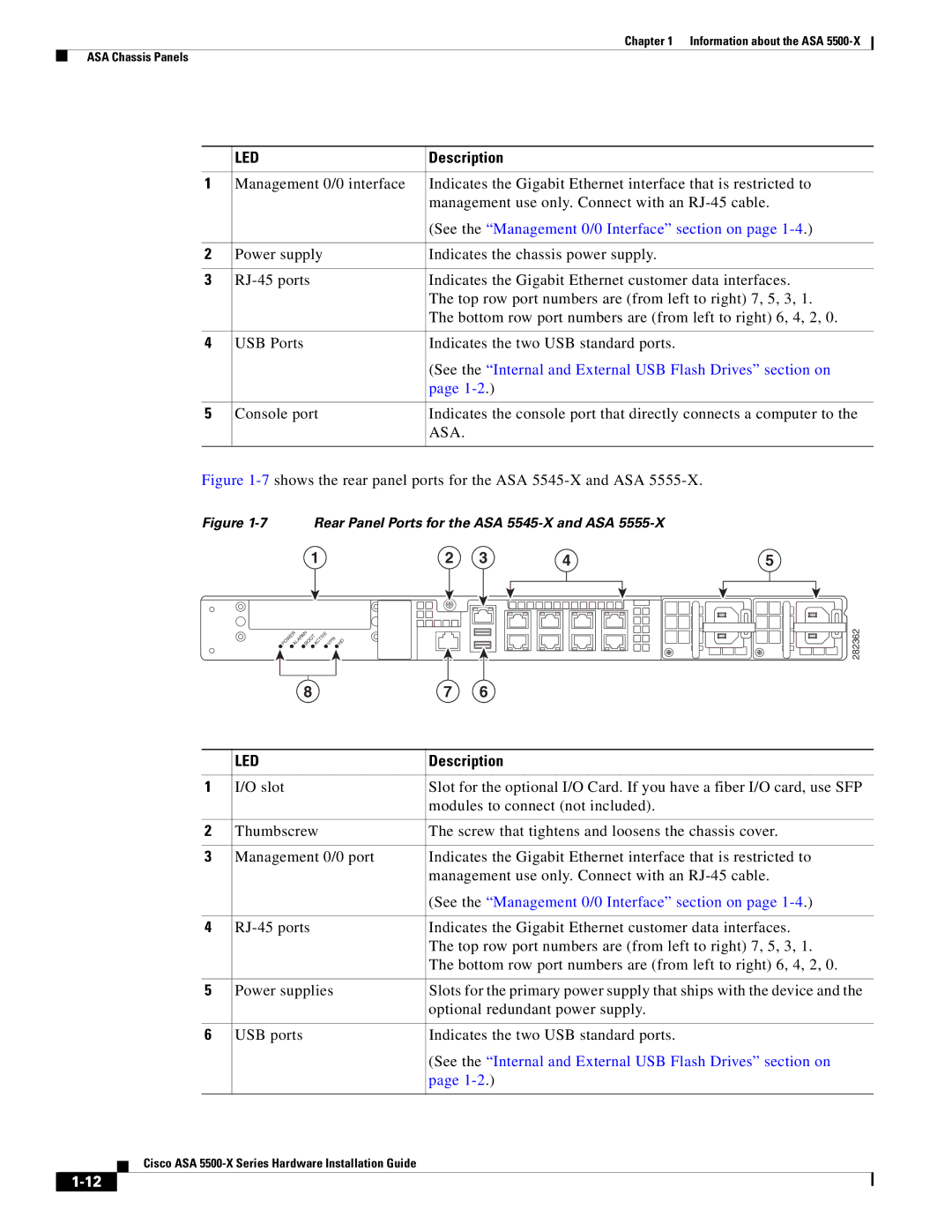
Figure 1-7 shows the rear panel ports for the ASA 5545-X and ASA 5555-X.
Figure 1-7 Rear Panel Ports for the ASA 5545-X and ASA 5555-X
1 | 2 | 3 | 4 | 5 |
POWERALARMvBOOTACTIVE VPN HD
8 | 7 | 6 |
282362
| LED | Description |
|
|
|
1 | I/O slot | Slot for the optional I/O Card. If you have a fiber I/O card, use SFP |
|
| modules to connect (not included). |
|
|
|
2 | Thumbscrew | The screw that tightens and loosens the chassis cover. |
|
|
|
3 | Management 0/0 port | Indicates the Gigabit Ethernet interface that is restricted to |
|
| management use only. Connect with an |
|
| (See the “Management 0/0 Interface” section on page |
|
|
|
4 | Indicates the Gigabit Ethernet customer data interfaces. | |
|
| The top row port numbers are (from left to right) 7, 5, 3, 1. |
|
| The bottom row port numbers are (from left to right) 6, 4, 2, 0. |
|
|
|
5 | Power supplies | Slots for the primary power supply that ships with the device and the |
|
| optional redundant power supply. |
|
|
|
6 | USB ports | Indicates the two USB standard ports. |
|
| (See the “Internal and External USB Flash Drives” section on |
|
| page |
|
|
|