Corporate Headquarters
Text Part Number OL-4803-01
Copyright 2003, Cisco Systems, Inc All rights reserved
N T E N T S
Iii
Safety Recommendations
Dhcp
CA0UID CA1UID
NPrintf TraceFlags
Vii
Installation and Upgrade Issues
Viii
This preface includes the following sections
Objectives
Audience
Organization and Use
Conventions
Organization
Chapter Description
Bewaar Deze Instructies
Xii
Warnung Wichtige Sicherheitshinweise
Avvertenza Importanti Istruzioni Sulla Sicurezza
Aviso Instruções Importantes DE Segurança
Xiii
Xiv
Related Documentation
Use this guide in conjunction with these documents
Obtaining Documentation
Cisco.com
Documentation CD-ROM
Ordering Documentation
Obtaining Technical Assistance
Documentation Feedback
You can order Cisco documentation in these ways
Xvi
Technical Assistance Center
Cisco TAC Website
Cisco TAC Escalation Center
Xvii
Obtaining Additional Publications and Information
Xviii
Cisco Analog Telephone Adaptor Overview
Overview of Media Gateway Control Protocol
Pstn
Hardware Overview
Link LED
Function Button
Software Features
Cisco ATA supports the following protocols and services
Mgcp Versions
Voice Codecs Supported
Additional Supported Signaling Protocols
Cisco ATA Mgcp Services
Other Supported Protocols
729A 729B 729.AB
Service Parameter
Fax Services
Supplementary Services that the Cisco ATA Provides
Supplementary Services that the Call Agent Provides
Installation and Configuration Overview
Signaling image by using the Tftp server-upgrade method or
Manual-upgrade method
Action Reference
OL-4803-01
Installing the Cisco ATA
What the Cisco ATA Package Includes
Safety Recommendations
Network Requirements
What You Need
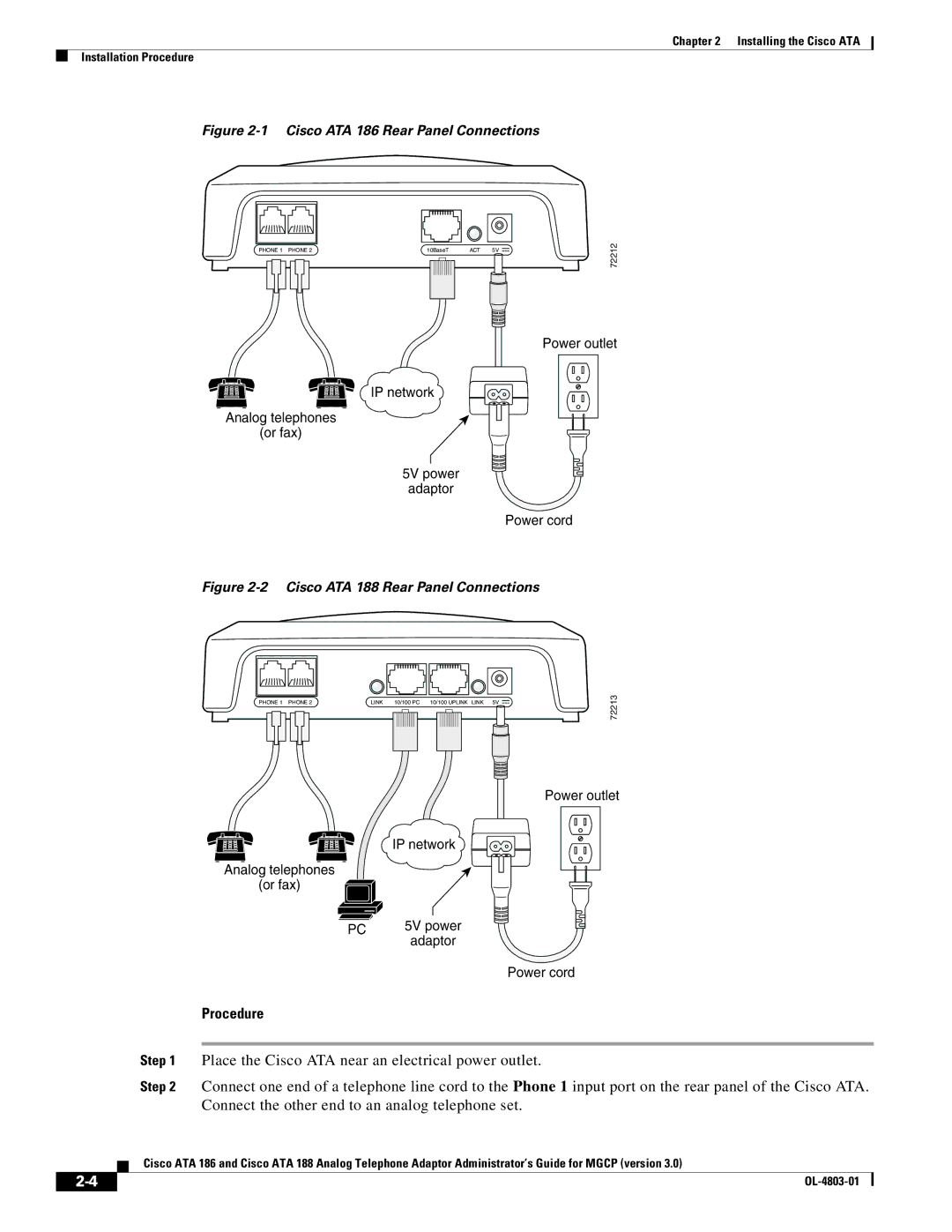
Installation Procedure
5V power adaptor Power cord
Procedure
Cisco ATA 186 Rear Panel Connections
Installing the Cisco ATA Installation Procedure
Power-Down Procedure
Configuring the Cisco ATA for Mgcp
Default Boot Load Behavior
Page
VLANSetting
Feature
Parameter and Bits Reference
Bits
Hexadecimal format, this value is 0x01cc002b
Steps Needed to Configure the Cisco ATA
Basic Configuration Steps in a Tftp Server Environment
Tftp server at boot up time
Action Reference
Basic Configuration Steps in a Non-TFTP Server Environment
Action
Configurable Features and Related Parameters
Configuring the Cisco ATA Using a Tftp Server
Setting Up the Tftp Server with Cisco ATA Software
Creating Unique and Common Cisco ATA Configuration Files
Save this file of Cisco ATA-specific parameters as
Syntax
Using atapname.exe Tool to Obtain MAC Address
Cfgfmt -mgcp -tptag.datata0a141e28323c.txt ata0a141e28323c
Command Output
Using Encryption With the cfgfmt Tool
Command Example
Total Binary Output Size
Non-zero
Syntax Definitions-Required Parameters
Syntax of the cfgfmt tool follows
Syntax Definitions-Options
Examples of Upgrading to Stronger Encryption Key
Syntax examples
Ata102030405060 is unencrypted
Atadefault.cfg Configuration File
Using a Dhcp Server
Using a Dhcp Server,
Other Dhcp Options You Can Set
Voice Configuration Menu
Without Using a Dhcp Server
Using the Voice Configuration Menu
Voice Menu Number Features
Entering Alphanumeric Values
Voice Menu Number
Key Alphanumeric Characters
Cisco ATA Web Configuration
Resetting the Cisco ATA to Factory Default Values
Cisco ATA Web Configuration
Refreshing or Resetting the Cisco ATA
Procedure to Reset the Cisco ATA
Upgrading the Mgcp Signaling Image
Procedure to Refresh the Cisco ATA
Cisco ATA-Supported Mgcp Services
Important Basic Mgcp Services
Setting the Codec
Configuring Refresh Interval
Required Parameters
Additional Mgcp Services
Endpoints and Connections
Call Agent Redundancy with Configuration Parameters
Mgcp Endpoint Device Type
Cisco ATA Registration Process with Mgcp
Syntax Type
Complete Reference Table of all Cisco ATA Mgcp Services
Rsip Message for Disconnect State
Configurable Feature Related Parameter
Supported Signals and Events
Supported Mgcp Connection Modes
Supported Local Connection Options
Related CIsco ATA Parameter
Code Description Type
Intermittent dial tone Timer Dtmf input
NCS 1.0 L-Package Supported by the Cisco ATA with Mgcp
Wt1, wt2, wt3, wt4 Call-waiting tone Dtmf tones wildcard
Mgcp 0.1-1.0 L-Package Supported by the Cisco ATA with Mgcp
Mgcp 0.1-1.0 G-Package Supported by the Cisco ATA with Mgcp
Operation failed Rbk### Rt@connection id
Commands Supported with Mgcp
Mgcp 0.1-1.0 D-Package Supported by the Cisco ATA with Mgcp
Parameter Usage
Parameters in Commands Sent to the Call Agent
Parameters in Responses Sent to the Call Agent
Mgcp Embedded Events
Example HdA, ESdl, Roc, 0-9#TD, D1xxxxxxxxxx9011x.T
OL-4803-01
Parameters and Defaults
Configuration Text File Template
IP address e.g Integer 32-bit integer Numeric digit string
UIPassword
User Interface UI Security Parameter
Value Type
Range
Parameters for Configuration Method and Encryption
UseTFTP
TftpURL
CfgInterval
Maximum 31 characters
905
EncryptKey
EncryptKeyEx
Not applicable for this parameter
Network Configuration Parameters
Range Default
Voice Configuration Menu Access Code Related Parameters
StaticIp
StaticRoute
IP address
916
StaticNetMask
255.255.255.0
Vlan Setting
Related parameter
Examples
Mgcp Configuration Parameters
CA0orCM0
CA1orCM1
Specify the ID of the primary Call Agent in this parameter
Value Types
Voice Configuration Menu Access Codes
EPID0orSID0 and EPID1orSID1
Integer
PrfCodec
LBRCodec
MGCPPort
300
2427
201
RetxLim
MediaPort
RetxIntvl
MGCPVer
Domain
205
Alphanumeric
931
Audio Configuration Parameters
CodecName
Bit Number Definition
Default Names
AudioMode
CallerIdMethod
Operational Parameters
NumTxFrames
Parameters and Defaults Operational Parameters
FXSInputLevel
FXSOutputLevel
ConnectMode
371
0x90000400
311
Bit Number
SigTimer
OpFlags
0x2
Bit Number Definition
255
Tone Configuration Parameters
0x000068B8
Tone Parameter Syntax-Basic Format
Each tone is specified by nine integers, as follows
Each tone is specified by 11 integers, as follows
Tone Parameter Syntax-Extended Formats
Extended Format a
Extended Format B
Cadence With Two On-Off Pairs
Cadence with Three On-Off Pairs
Component Setting Explanation
ReorderTone Parameter Example1
ReorderTone Parameter Example
Default values using the Basic format
Recommended Values
Specific Tone Parameter Information
DialTone
BusyTone
ReorderTone
RingbackTone
CallWaitTone
922
923
AlertTone
OffTime-2400 TotalToneTime-4800
924
925
Diagnostic Parameters
Default Recommended Values
RingCadence
NPrintf
TraceFlags
SyslogIP
Extended IP address
0x00000000
SyslogCtrl
Bit Number Type of Messages to Trace
CFGID-Version Parameter for Cisco ATA Configuration File
RTP statistics messages Reserved
OL-4803-01
Configuring and Debugging Fax Services
Using Fax Pass-through Mode
Configuring the Cisco ATA for Fax Pass-through mode
Fax Pass-through mode requires configuring two parameters
This setting translates to the following bitmap
AudioMode
Configuring Cisco IOS Gateways to Enable Fax Pass-through
Recommended Setting
This setting translates to the bitmap
ConnectMode
Enable Fax Pass-through Mode
Run the following command
Disable Fax Relay Feature
Perform the command
Using FAX Mode
Configuring the Cisco ATA for Fax Mode
Debugging the Cisco ATA 186/188 Fax Services
Configuring the Cisco IOS Gateway for Fax Mode
Common Problems When Using IOS Gateways
Problem Action
Using prserv for Diagnosing Fax Problems
Cisco ATA, and 0x0012XXXX for the Phone 2 port
For fax pass-through mode, AudioMode should be set to
Port
Prserv Overview
Analyzing prserv Output for Fax Sessions
Log event Description
Decoding timestamp was set to timestamp2
That the first RTP packet that the Cisco ATA received was
Encoded for channel
Originating-Gateway Example
Possible Reasons for Failure
To use rtpcatch, follow these steps
Using rtpcatch for Diagnosing Fax Problems
Rtpcatch Overview
Example of rtpcatch
Output Files
Explanation
CED tone Detected
Fax relay mode Cisco fax relay mode
Analyzing rtpcatch Output for Fax Sessions
Analysis
Both sides use G.711 for the entire fax session
Using rtpcatch to Analyze Common Causes of Failure
Example 6-3 Fax Pass-through Mode
Possible Cause for Failure
Cisco fax relay option is not disabled on the gateway
Possible Causes for Failure
Example 6-9 Fax Pass-through Mode Failure
Rtpcatch Limitations
Definitions
Upgrading the Signaling Image from a Tftp Server
Syntax of upgradecode Parameter
Process
Upgrading the Signaling Image Manually
Upgradecode parameter value could be
Upgrade Requirements
Preliminary Steps
Running the Executable File
Syntax
Upgrade Procedure
To perform the upgrade, follow these steps
Confirming a Successful Signaling Image Upgrade
Using a Web Browser
OL-4803-01
Troubleshooting
General Troubleshooting Tips
Symptoms and Actions
Installation and Upgrade Issues
Debugging
You should also have access to a sniffer or LAN analyzer
2* 1 1* 2* 8* 1 1* 7* 8* 1 1* 9* 0* 1 1* 9* 0* 0
Using System Diagnostics
Message Syntax
PriorityTimeOffset Ataip tag chMessage
Syntax Definitions
Example-TFTP messages
Example-ARP Message
Example-DHCP Messages
Example-Cisco ATA Event Messages
Example-Cisco ATA Configuration Update Message
Example-System Reboot Message
Example-RTP Statistic Messages
Local Tone Playout Reporting
Example-Fax Event Messages
Tone Type ID Description
Bit Number Description Boolean Value
Obtaining Network Status After Getting IP Connectivity
Bit Number Description
Cisco ATA failed to upgrade to the downloaded image file
Configuration file is not found
Bad configuration file
Checksum error for configuration file
Dhcp Status Html
Real-Time Transport Protocol RTP Statistics Reporting
Ring Load per RJ-11 FXS Port Maximum Distance
Frequently Asked Questions
Resetting Cisco ATA counters
Contacting TAC
OL-4803-01
Table A-1lists codes to return basic Cisco ATA information
Voice Menu Option Code Description
916 IP address of the primary DNS server
DNS 2 IP
Tftp URL
OL-4803-01
Physical Specifications
This section describes Cisco ATA specifications
Dimensions Weight
Specification
Electrical Specifications for Cisco ATA
Environmental Specifications
Description Specification
Physical Interfaces
Tip/ring interfaces for each RJ-11 FXS port Slic
Ringing Characteristics
Software Specifications
Appendix B Cisco ATA Specifications Software Specifications
Sccp
OL-4803-01
Mgcp Call Flows
Appendix C Mgcp Call Flows
Step Action Log
Cisco ATA 1 dials 6-Cisco ATA 1 to Call Agent
Cisco ATA 2 phone rings and displays Cisco ATA 1 ID on CID
Device-Call Agent to Cisco ATA
OK-Cisco ATA 2 to Call Agent
Routing Update Protocol RTP Media stream is now enabled on
RTP Media stream is now enabled on Cisco ATA 1. Both
Cisco ATA 2-Call Agent to Cisco ATA
Ringback stops on Cisco ATA 1-Call Agent to Cisco ATA
ATA 2 Connection mode changes to receive-only-Call Agent to
Cisco ATA 2 hangs up-Cisco ATA 2 to Call Agent
Cisco ATA 2 Connection is deleted-Call Agent to Cisco ATA
Agent to Cisco ATA
Recommended Cisco ATA Tone Parameter Values by Country
OL-4803-01
Table D-1 Argentina
Table D-5 Brazil
Table D-9 Czech Republic
Table D-13 France
Table D-17 Hungary
Table D-21 Ireland
Table D-25 Korea
Table D-29 Netherlands
Table D-33 Panama
Table D-37 Portugal
Table D-41 Slovakia
Table D-45 Sweden
Parameter Recommended Values
OL-4803-01
GL-1
GL-2
GL-3
GL-4
GL-5
Signaling connection control part
Messages can be part of Sgcp and Mgcp messages
GL-6
Business-class services for Internet telephony
Traffic
Allow you to define your own customized markup language
GL-7
GL-8
Bootload
Codec negotiation in sending fax
Codecs Cabling requirements LBRCodec Call Agent Supported
IN-1
IN-2
CallerIdMethod CfgInterval CodecName ConnectMode Dhcp
EncryptKey
IN-3
Debugging Services
Fax mode 6-1,6-6 Configuration
Fax relay disabling
IN-4
IN-5
IN-6
Cisco ATA RSIP*@ipaddress syntax setting
RTP payload type RTP statistics reporting
IN-7
IN-8