Customer Order Number OL-4008-01
Corporate Headquarters
Copyright 2003, Cisco Systems, Inc All rights reserved
Iii
N T E N T S
Safety Recommendations
ToConfig
Dhcp
Vii
DNS1IP DNS2IP
Viii
Using FAX Mode
Contacting TAC
OL-4008-01
Audience
Overview
This preface includes the following sections
Xii
Organization
Conventions
Chapter Description
Xiii
Xiv
Related Documentation
Ordering Documentation
Obtaining Documentation
World Wide Web
Documentation CD-ROM
We appreciate your comments
Obtaining Technical Assistance
Cisco.com
Technical Assistance Center
Cisco TAC Escalation Center
Cisco TAC Web Site
Xvii
Xviii
Cisco Analog Telephone Adaptor Overview
Cisco ATA 186 as Endpoint in an H.323 Network
Gateways
Terminals
MCUs
Gatekeepers
Proxy Server
Cisco ATA 186-Rear View
Hardware Overview
Function Button
Other Supported Protocols
Software Features
Additional Supported Signaling Protocols
Voice Codecs Supported
Cisco ATA H.323 Services
Action Reference
Installation and Configuration Overview
Fax Services
Supplementary Services
Image
Upgrading the Cisco ATA Signaling
Image by using the Tftp server-upgrade method or
Manual-upgrade method
Safety Recommendations
Installing the Cisco ATA
What the Cisco ATA Package Includes
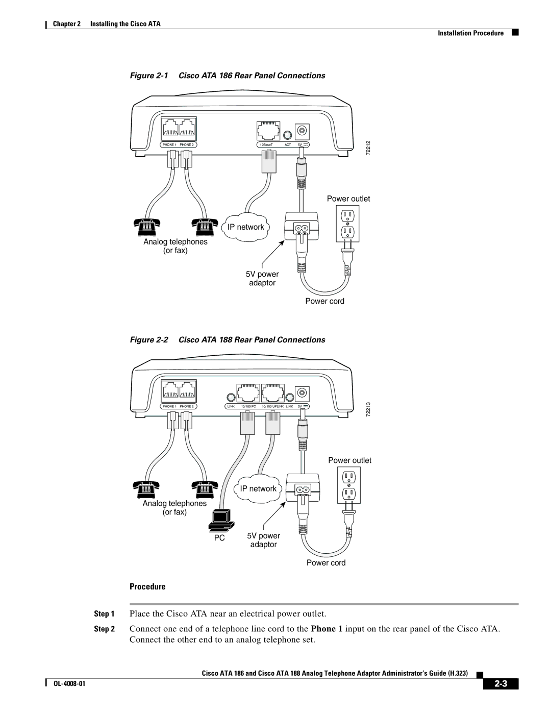
Installation Procedure
What You Need
Cisco ATA 186 Rear Panel Connections
Procedure
Installing the Cisco ATA Installation Procedure
Power-Down Procedure
OL-4008-01
Configuring the Cisco ATA for H.323
Default Boot Load Behavior
OpFlags,
VLANSetting,
Parameter and Bits Reference
OpFlags
Example
VLANSetting
Feature
Bits
Upgrading the Signaling Image from a Tftp Server
Steps Needed to Configure the Cisco ATA
Basic Configuration Steps in a Tftp Server Environment
Atadefault.cfg Configuration File,
Refreshing or Resetting the Cisco ATA,
Basic Configuration Steps in a Non-TFTP Server Environment
Configuring the Cisco ATA to Obtain its
Configuration File from the Tftp Server,
Setting Up the Tftp Server with Cisco ATA Software
Configuring the Cisco ATA Using a Tftp Server
Configurable Features and Related Parameters
Creating Unique and Common Cisco ATA Configuration Files
Syntax
Save this file of Cisco ATA-specific parameters as
Command Example
Using atapname.exe Tool to Obtain MAC Address
Command Output
Syntax examples
Using the EncryptKey Parameter and cfgfmt Tool
Using a Dhcp Server,
Atadefault.cfg Configuration File
Without Using a Dhcp Server,
Using a Dhcp Server
Other Dhcp Options You Can Set
Without Using a Dhcp Server
DNS1IP DNS2IP Ntpip
Voice Configuration Menu
Voice Menu Number Features
Using the Voice Configuration Menu
Key Alphanumeric Characters
Entering Alphanumeric Values
Resetting the Cisco ATA to Factory Default Values
Cisco ATA Web Configuration
Where ipaddress is the IP address of the Cisco ATA
UID0
OpFlags, page 5-33-Bit
Web Interface Access-Control Configuration
Refreshing or Resetting the Cisco ATA
Related Parameter
Http Refresh and Reset Access-Control Configuration
Upgrading the H.323 Signaling Image
Http Procedure to Refresh the Cisco ATA
Http Procedure to Reset the Cisco ATA
OL-4008-01
Required Parameters
Important Basic H.323 Services
Setting the Signaling Image to H.323 Mode
UID0, UID1,
Setting Up User IDs for the Cisco ATA
Using the Cisco ATA with an H.323 Gatekeeper
Related Configuration Parameters
AltGk, AltGkTimeOut, ConnectMode,
Setting Up Gatekeeper Time-To-Live Value
Setting Up an Alternate H.323 Gatekeeper
LoginID0, LoginID1, UID0, UID1,
Establishing Authentication with Cisco H.323 Gatekeeper
Using Multiple Cisco ATAs Without an H.323 Gatekeeper
Using the Cisco ATA Without an H.323 Gatekeeper
Gateway, GkOrProxy,
LBRCodec, AudioMode,
Additional H.323 Services
Setting the Audio Codecs
IPDialPlan,
Configuring Billable Features
Configuring Audio Packet Settings
Configuring the Mixing of Call Waiting Tone and Audio
Configuring the Call Waiting Permanent Default Setting
Configuring the Cisco ATA Refresh Interval
Configuring Hook Flash Timing
Debugging Diagnostics
Configuring On-hook delay
Configuring Reverse Audio Cut-Through Behavior
Configuring Supplementary Service Behavior and Parameters
Selecting Dtmf and Hookflash Transmission Methods
Polarity Settings
Network Timing
Progress Tones
DialPlan,
Setting Dial Plans
Selecting H.323 Connection and H.245 Transmission Methods
ConnectMode, page 5-28-Bits 0
Configurable Features Related Parameters
OL-4008-01
Parameters and Defaults
Configuration Text File Template
Sections that follow describe these parameters
UIPassword
This section contains only one parameter-UIPassword
User Interface UI Parameter
Parameters for Configuration Method and Encryption
Configuration-Complete Parameter
ToConfig
TftpURL
Settings
Range Default Voice Configuration Menu Access Code
UseTFTP
UseTFTP, TftpURL,
CfgInterval
EncryptKey
UseTFTP, CfgInterval,
320
Network Parameters
DHCP, StaticIp, StaticRoute, StaticNetMask,
DHCP, StaticRoute, StaticNetMask,
Voice Configuration Menu Access Code Related Parameters
StaticIp
StaticRoute
255.255.255.0
Account Information Parameters
StaticNetMask
DHCP, StaticIp, StaticNetMask,
This parameter is the password for the Phone 1 port
UID1, PWD0, PWD1, UseLoginID, LoginID0, LoginID1,
UID0, PWD0, PWD1, UseLoginID, LoginID0, LoginID1,
UID0, UID1, PWD1, UseLoginID, LoginID0, LoginID1, AutMethod,
Gateway
This parameter is the password for the Phone 2 port
LoginID0
UseLoginID
LoginID1, PWD0, PWD1, UseLoginID, AutMethod,
Bitmap
LoginID1
LoginID0, PWD0, PWD1, UseLoginID, AutMethod,
AutMethod
Gatekeeper Parameters
LoginID0, LoginID1, PWD0, PWD1, NTPIP, AltNTPIP,
GkOrProxy, AltGk, AltGkTimeOut, GkTimeToLive, GkId,
AltGk, AltGkTimeOut, GkTimeToLive, GkId,
30 to 4294967295 seconds
AltGkTimeOut
AltGk
Integer
Not specified
Default Range
GkTimeToLive
GkId
UseSIP
Mode Parameter
Use H.323 mode -Use SIP mode
Operating Parameters
LBRCodec
DNS2IP, UDPTOS, SigTimer, OpFlags, VLANSetting,
UDPTOS, VLANSetting,
MediaPort
LBRCodec, ConnectMode, RxCodec,
AudioMode
RxCodec, TxCodec,
AudioMode, page 5-20-Bits 1 TxCodec, RxCodec, NumTxFrames,
Bit Number Definition
RxCodec
LBRCodec, NumTxFrames, TxCodec, AudioMode,
TxCodec
LBRCodec, NumTxFrames, RxCodec, AudioMode,
Examples
NumTxFrames
LBRCodec, RxCodec, TxCodec,
Bit Number
CallFeatures
CallFeatures, CallCmd, CallerIdMethod, SigTimer,
PaidFeatures
315
CallerIdMethod
0x00019e60
Polarity
316
ConnectMode
Use G.711µ-law for fax pass-through codec
TimeZone
Use G.711A-law for fax pass-through codec
AltNTPIP, TimeZone,
AltNTPIP
NTPIP, AltNTPIP,
141
916
NTPIP, TimeZone,
917
SigTimer
OpFlags
TftpURL, DHCP, VLANSetting,
VLANSetting
324
Optional Feature Parameters
NPrintf
0x0000002b
RingOnOffTime
Default Recommended Values
IPDialPlan
Additional DialPlan Information
DialPlan
Following dial plan
About Dial Plan Commands
Following dial plans
Dial Plan Blocking In Rule
Rule to Support Dial Prefix
Rule to Support Hotline/Warmline
Each tone is specified by nine integers, as follows
Call-Progress Tone Parameters
List of Call-Progress Tone Parameters
Tone Parameter Syntax
Recommended Values
How to Calculate Scaling Factors
Use the following formula to calculate the scaling factor a
Specific Call-Progress Tone Parameter Information
Default values for the nine-integer array
920
921
Cisco ATA plays the busy tone when the callee is busy
922
924
923
925
CallCmd
Maximum of 248 characters
930
CallFeatures, PaidFeatures, CallerIdMethod, SigTimer,
OL-4008-01
Call Command Structure
Call Commands
CallCmd string has the following structure
Syntax
Identifier Context State of Cisco ATA
Context-Identifiers
Identifier Action
Input Sequence Identifiers
Action Identifiers
Identifier Input Sequence
Call Command Example
Hook-flash Cancel-the-call-attempt Retrieve-the-waiting-call
Table Notations
Call Command Behavior
Call Command Default
Sweden Call Command Default
Call Command Behavior
CWT
WFE cancels the call-Stop CWT and revert to Connected state
Call Command Behavior
Call Command Behavior
OL-4008-01
Using Fax Pass-through Mode
Configuring and Debugging Fax Services
AudioMode, ConnectMode,
Configuring the Cisco ATA for Fax Pass-through mode
This setting translates to the following bitmap
AudioMode
Enable Fax Pass-through Mode, Disable Fax Relay Feature,
Configuring Cisco IOS Gateways to Enable Fax Pass-through
Recommended Setting
This setting translates to the bitmap
Run the following command
Enable Fax Pass-through Mode
Perform the command
Disable Fax Relay Feature
Configuring the Cisco ATA for Fax Mode
Using FAX Mode
Common Problems When Using IOS Gateways
Debugging the Cisco ATA 186/188 Fax Services
Configuring the Cisco ATA for Fax Mode on a Per-Call Basis
Configuring the Cisco IOS Gateway for Fax Mode
Port
Problem Action
Cisco ATA, and 0x0012XXXX for the Phone 2 port
For fax pass-through mode, AudioMode should be set to
Prserv Overview, Analyzing prserv Output for Fax Sessions,
Using prserv for Diagnosing Fax Problems
Prserv Overview
Analyzing prserv Output for Fax Sessions
Terminating-Gateway Example
Log event Description
Possible Reasons for Failure
Originating-Gateway Example
Rtpcatch Overview
Using rtpcatch for Diagnosing Fax Problems
To use rtpcatch, follow these steps
Output Files
Example of rtpcatch
Explanation
CED tone Detected
Both sides use G.711 for the entire fax session
Fax relay mode Cisco fax relay mode
Analyzing rtpcatch Output for Fax Sessions
Analysis
Example 7-4 T38 Fax Relay Mode
Possible Cause for Failure
Using rtpcatch to Analyze Common Causes of Failure
Cisco fax relay option is not disabled on the gateway
Possible Causes for Failure
Example 7-9 Fax Pass-through Mode Failure
Rtpcatch Limitations
Syntax of upgradecode Parameter
Upgrading the Signaling Image from a Tftp Server
Definitions
Preliminary Steps, Running the Executable File,
Upgrading the Signaling Image Manually
Upgradecode parameter value could be
Process
Preliminary Steps
Upgrade Requirements
Running the Executable File
Syntax
Upgrade Procedure and Verification
To perform the upgrade, follow these steps
Procedure to Upgrade Signaling Image
Using a Web Browser
Confirming a Successful Signaling Image Upgrade
Using a Web Browser, Using the Voice Configuration Menu,
Using the Voice Configuration Menu
General Troubleshooting Tips
Troubleshooting
Symptoms and Actions
Installation and Upgrade Issues
Debugging
Ring Load per RJ-11 FXS Port Maximum Distance
Frequently Asked Questions
Feet 975 m
Feet 762 m
Contacting TAC
OL-4008-01
Cancelling a Supplementary Service
Changing Call Commands
Common Supplementary Services
Call-Waiting Caller ID
Caller ID
Making a Conference Call in the United States
Calling Line Identification Presentation
Making a Conference Call in Sweden
Call Waiting in the United States
Call Waiting in Sweden
Calling Line Identification Restriction in Sweden
About Calling Line Identification Restriction
Voice Menu Option Code Description
Table B-1lists codes to return basic Cisco ATA information
Password associated with the secondary phone line
Table B-2lists configuration codes
Password associated with the primary phone line
UID0 or LoginID0
User ID telephone number for the Phone 2 port
User ID telephone number for the Phone 1 port
Option Code Description
Specification
Physical Specifications
This section describes Cisco ATA specifications
Dimensions Weight
Description Specification
Electrical Specifications
Environmental Specifications
Immunity Specifications
Software Specifications
Ringing Characteristics
Physical Interfaces
Appendix C Cisco ATA Specifications Software Specifications
Sccp
OL-4008-01
Supported H.323 Messages
Signaling
Endpoint-to-Gatekeeper Registration
Signaling Scenarios
Step Action Description
Table D-2 Log Listings
Table D-2 Log Listings
Endpoint-to-Endpoint Call Setup with a Common Gatekeeper
Step
Table D-4 Log Listings
Table D-4 Log Listings
Table D-4 Log Listings
Table D-4 Log Listings
Table D-4 Log Listings
Table D-4 Log Listings
Table D-4 Log Listings
Call Setup from H.323 Network to Circuit Switched Network
CSN/PSTN
Action Description
Step
Table D-6 Log Listings
Table D-6 Log Listings
Table D-6 Log Listings
Table D-6 Log Listings
Table D-6 Log Listings
Table D-6 Log Listings
Table D-6 Log Listings
Table D-6 Log Listings
Table D-6 Log Listings
Table D-6 Log Listings
Table D-6 Log Listings
Table D-6 Log Listings
Table D-6 Log Listings
Table D-6 Log Listings
Table D-6 Log Listings
Table D-6 Log Listings
Null
Table D-6 Log Listings
GL-1
GL-2
GL-3
GL-4
Messages can be part of Sgcp and Mgcp messages
Signaling connection control part
GL-5
GL-6
GL-7
Business-class services for Internet telephony
Traffic
Allow you to define your own customized markup language
GL-8
IN-1
Numerics
IN-2
Ethernet ports Example configuration text file
Environmental specifications C-2
IN-3
Hotline/warmline Http refresh
Http reset
IN-4
IN-5
Plar
IN-6
RJ-45 LED
IN-7
Troubleshooting
IN-8