Making Serial Data Connections
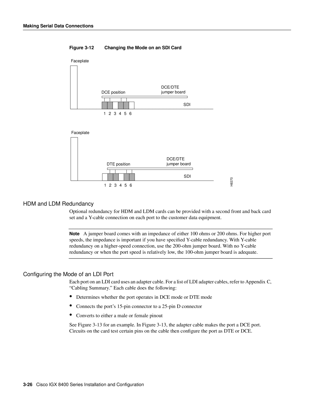
Figure 3-12 Changing the Mode on an SDI Card
Faceplate
|
|
|
|
| DCE/DTE | |
DCE position | jumper board | |||||
|
|
|
|
|
|
|
|
|
|
|
|
|
|
SDI
1 2 3 4 5 6
Faceplate
|
|
|
|
|
| DCE/DTE |
| DTE position | jumper board | ||||
|
|
|
|
|
| SDI |
1 | 2 | 3 | 4 | 5 | 6 |
|
H8370
HDM and LDM Redundancy
Optional redundancy for HDM and LDM cards can be provided with a second front and back card set and a
Note A jumper board comes with an impedance of either 100 ohms or 200 ohms. For higher port speeds, the impedance is important if you have specified
Configuring the Mode of an LDI Port
Each port on an LDI card uses an adapter cable. For a list of LDI adapter cables, refer to Appendix C, “Cabling Summary.” Each cable does the following:
•
•
•
Determines whether the port operates in DCE mode or DTE mode
Connects the port’s
Converts to either a male or female pinout
See Figure