Cisco Systems IGX 8400 Series manual Frame Relay Card Redundancy

Models: IGX 8400 Series

1 52
Download 52 pages 51.44 Kb
Page 33
Image 33
Frame Relay Card Redundancy

Making Frame Relay Connections

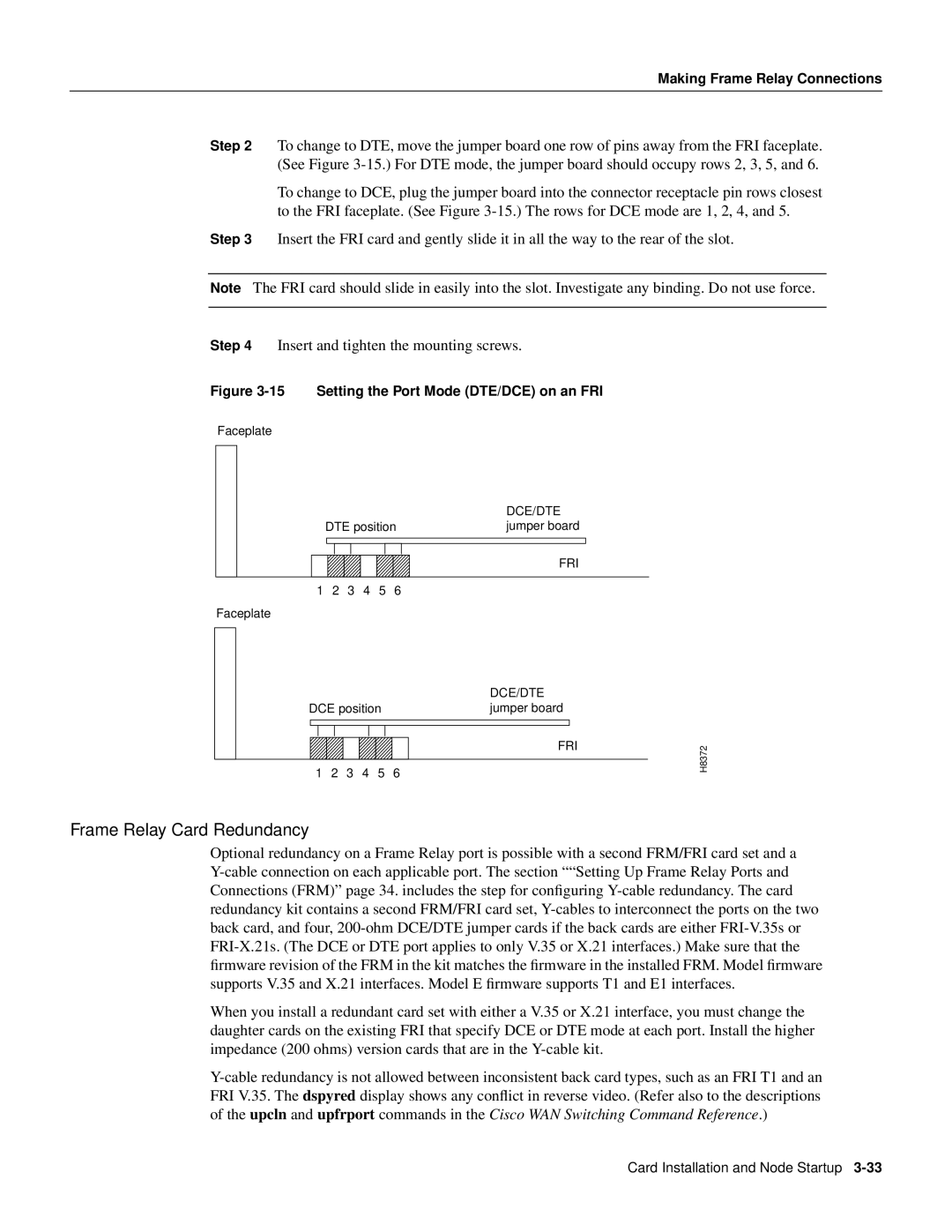
Step 2 To change to DTE, move the jumper board one row of pins away from the FRI faceplate. (See Figure 3-15.) For DTE mode, the jumper board should occupy rows 2, 3, 5, and 6.

To change to DCE, plug the jumper board into the connector receptacle pin rows closest to the FRI faceplate. (See Figure 3-15.) The rows for DCE mode are 1, 2, 4, and 5.

Step 3 Insert the FRI card and gently slide it in all the way to the rear of the slot.

Note The FRI card should slide in easily into the slot. Investigate any binding. Do not use force.

Step 4 Insert and tighten the mounting screws.

Figure 3-15 Setting the Port Mode (DTE/DCE) on an FRI

Faceplate


DCE/DTE


DTE position

jumper board


FRI

1

2

3

4

5

6


Faceplate


DCE/DTE

DCE position

jumper board


FRI

1 2 3 4 5 6

H8372

Frame Relay Card Redundancy

Optional redundancy on a Frame Relay port is possible with a second FRM/FRI card set and a Y-cable connection on each applicable port. The section ““Setting Up Frame Relay Ports and Connections (FRM)” page 34. includes the step for configuring Y-cable redundancy. The card redundancy kit contains a second FRM/FRI card set, Y-cables to interconnect the ports on the two back card, and four, 200-ohm DCE/DTE jumper cards if the back cards are either FRI-V.35s or FRI-X.21s. (The DCE or DTE port applies to only V.35 or X.21 interfaces.) Make sure that the firmware revision of the FRM in the kit matches the firmware in the installed FRM. Model firmware supports V.35 and X.21 interfaces. Model E firmware supports T1 and E1 interfaces.

When you install a redundant card set with either a V.35 or X.21 interface, you must change the daughter cards on the existing FRI that specify DCE or DTE mode at each port. Install the higher impedance (200 ohms) version cards that are in the Y-cable kit.

Y-cable redundancy is not allowed between inconsistent back card types, such as an FRI T1 and an FRI V.35. The dspyred display shows any conflict in reverse video. (Refer also to the descriptions of the upcln and upfrport commands in the Cisco WAN Switching Command Reference.)

Card Installation and Node Startup 3-33

Page 33
Image 33
Cisco Systems IGX 8400 Series manual Frame Relay Card Redundancy