Making Frame Relay Connections
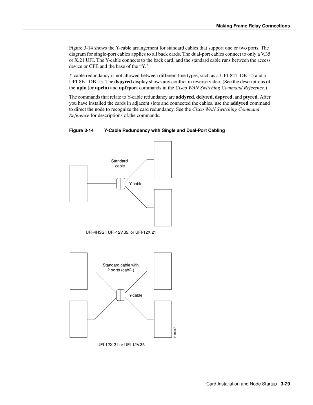
Figure 3-14 shows the Y-cable arrangement for standard cables that support one or two ports. The diagram for single-port cables applies to all back cards. The dual-port cables connect to only a V.35 or X.21 UFI. The Y-cable connects to the back card, and the standard cable runs between the access device or CPE and the base of the “Y.”
Y-cable redundancy is not allowed between different line types, such as a UFI-8T1-DB-15 and a UFI-8E1-DB-15. The dspyred display shows any conflict in reverse video. (See the descriptions of the upln (or upcln) and upfrport commands in the Cisco WAN Switching Command Reference.)
The commands that relate to Y-cable redundancy are addyred, delyred, dspyred, and ptyred. After you have installed the cards in adjacent slots and connected the cables, use the addyred command to direct the node to recognize the card redundancy. See the Cisco WAN Switching Command Reference for descriptions of.the commands.
Figure 3-14 Y-Cable Redundancy with Single and Dual-Port Cabling
Standard cable
Standard cable with
2 ports
H10047
Card Installation and Node Startup