Introduction ~ Controls and Connections | 5 |
C.▲/▼ These buttons scroll up and down through vertical programming options within a specific PSR1212 programming parameter or increases/decreases a numeric value.
D.Esc. This button steps you out of a selected parameter or moves you up one level in the menu. When a parameter has been displayed with the arrow buttons [C], you can select it with the Enter button [B] to modify it. Then, you can step out of the menu with the Esc button.
E.LED meter. This assignable,
F.Meter. Takes you directly to the Meter branch of the PSR1212’s LCD menu tree.
G.LED
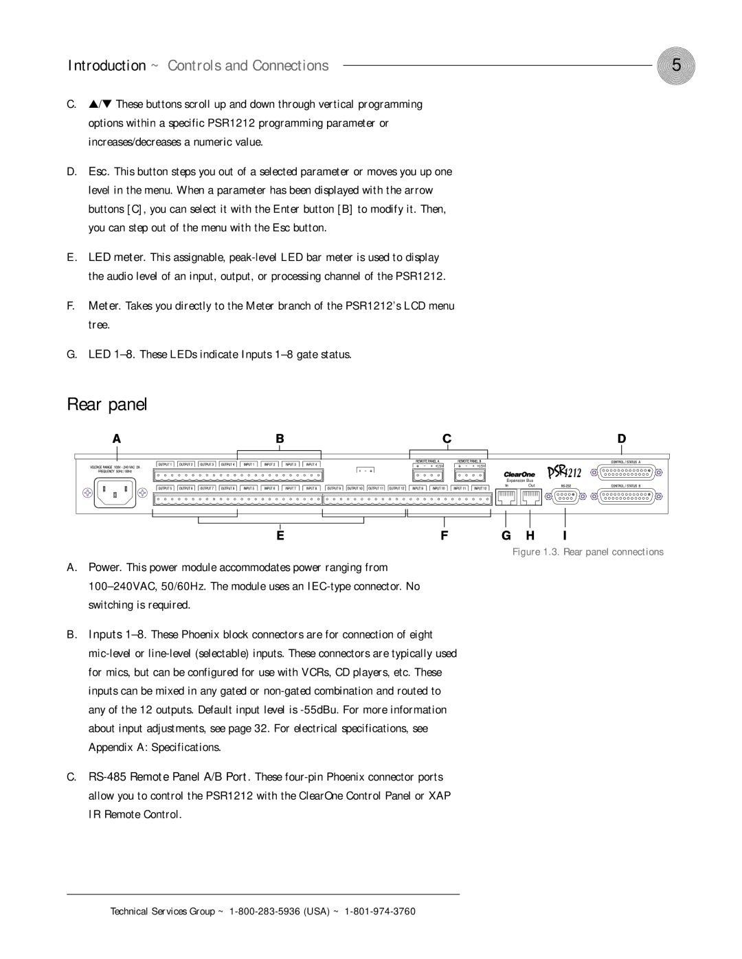
Rear panel
Expansion Bus | |
In | Out |
Figure 1.3. Rear panel connections
A.Power. This power module accommodates power ranging from
B.Inputs
C.