Installation
Figure 2-5. Removing terminal input block cover
3.Remove the input wiring entry port cover.
4.Pull the input wires through the conduit leading from the AC Mains, leaving about 2 ft (0.5 m) of wire hanging from the end. Attach a suitable connector to the end of the conduit.
5.Feed the wires through the wiring entry port, the entry compartment and the terminal input block compartment.
6.Connect the conduit to the panel. Measure wires, cut and strip 0.5 inch (1¼ cm) of insulation from the end of each incoming wire.
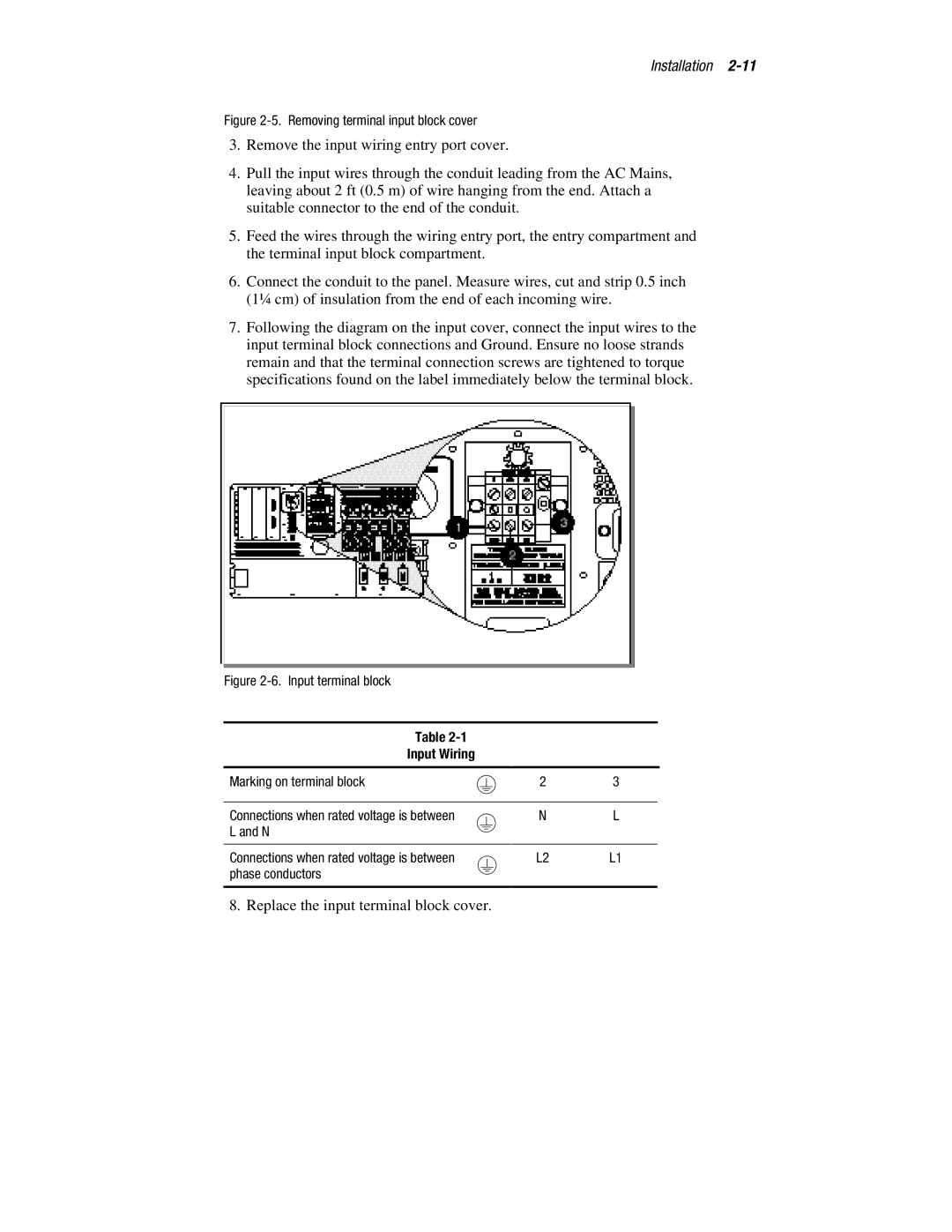
7.Following the diagram on the input cover, connect the input wires to the input terminal block connections and Ground. Ensure no loose strands remain and that the terminal connection screws are tightened to torque specifications found on the label immediately below the terminal block.
Figure 2-6. Input terminal block
Table
Input Wiring
Marking on terminal block | 2 | 3 |
|
|
|
Connections when rated voltage is between | N | L |
L and N |
|
|
|
|
|
Connections when rated voltage is between | L2 | L1 |
phase conductors |
|
|
|
|
|
8. Replace the input terminal block cover.
