INTERNAL
OPTO
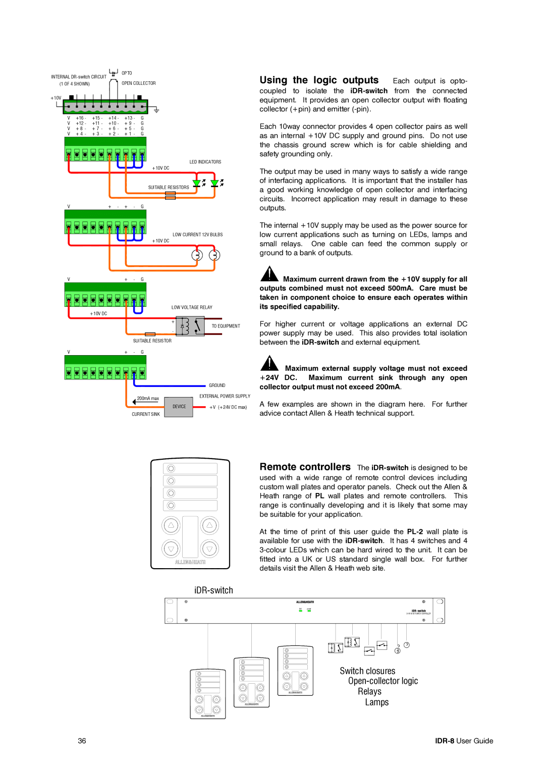
Using the logic outputs Each output is opto-
(1 OF 4 SHOWN) | OPEN COLLECTOR |
+10V |
|
|
V +16 - +15 - +14 - +13 - G | ||
V +12 - +11 - +10 - + 9 - G | ||
V + 8 - + 7 - + 6 - + 5 - G | ||
V + 4 - + 3 - + 2 - + 1 - G | ||
|
| LED INDICATORS |
|
| +10V DC |
|
| SUITABLE RESISTORS |
V | + - + - | G |
|
|
| LOW CURRENT 12V BULBS |
|
|
| +10V DC |
V | + | - | G |
|
|
| LOW VOLTAGE RELAY | |
| +10V DC |
|
|
|
|
|
| + | TO EQUIPMENT |
|
|
| - | |
|
|
|
| |
|
| SUITABLE RESISTOR |
| |
V | + | - | G |
|
|
|
|
| GROUND |
|
|
| 200mA max | EXTERNAL POWER SUPPLY |
|
|
|
| |
|
|
| DEVICE | +V (+24V DC max) |
|
| CURRENT SINK |
| |
coupled to isolate the
Each 10way connector provides 4 open collector pairs as well as an internal +10V DC supply and ground pins. Do not use the chassis ground screw which is for cable shielding and safety grounding only.
The output may be used in many ways to satisfy a wide range of interfacing applications. It is important that the installer has a good working knowledge of open collector and interfacing circuits. Incorrect application may result in damage to these outputs.
The internal +10V supply may be used as the power source for low current applications such as turning on LEDs, lamps and small relays. One cable can feed the common supply or ground to a bank of outputs.
![]() Maximum current drawn from the +10V supply for all outputs combined must not exceed 500mA. Care must be taken in component choice to ensure each operates within its specified capability.
Maximum current drawn from the +10V supply for all outputs combined must not exceed 500mA. Care must be taken in component choice to ensure each operates within its specified capability.
For higher current or voltage applications an external DC power supply may be used. This also provides total isolation between the
![]() Maximum external supply voltage must not exceed +24V DC. Maximum current sink through any open collector output must not exceed 200mA.
Maximum external supply voltage must not exceed +24V DC. Maximum current sink through any open collector output must not exceed 200mA.
A few examples are shown in the diagram here. For further advice contact Allen & Heath technical support.
Remote controllers The
used with a wide range of remote control devices including custom wall plates and operator panels. Check out the Allen & Heath range of PL wall plates and remote controllers. This range is continually developing and it is likely that some may be suitable for your application.
At the time of print of this user guide the
link power
24 IN 16 OUT SWITCH CONTROLLER
Switch closures
Relays
Lamps
36 |