Adding the iDR-switch Expander
link power
24 IN 16 OUT SWITCH CONTROLLER
100 - 240V~
FUSE: T500mAL
![]()
![]() WARNING
WARNING ![]()
THIS APPARATUS MUST BE EARTHED.
ATTENTION: REMPLACER LE FUSIBLE AVEC UN DES MEMES CARACTERISTIQUES.
FOR CONTINUED PROTECTION AGAINST RISK OF FIRE REPLACE FUSE WITH SAME TYPE AND RATING. CAUTION: RISK OF ELECTRIC SHOCK. DO NOT OPEN. AVIS: RISQUE DE CHOC ELECTRIQUE - NE PAS OUVRIR.
|
|
|
| +10V DC max total 500mA | V | SWITCH INPUTS | G | 24 23 | 22 21 | 20 19 | 18 17 | G | G | 16 15 | 14 13 | 12 11 | 10 9 | G | G | 8 7 | 6 5 | 4 3 | 2 1 | G | ||
|
|
|
| +10V |
| +10V |
|
|
|
|
|
|
|
|
|
|
|
|
|
|
|
|
|
| ||
|
|
|
| open collector | + | opto |
| 2K2 |
|
|
|
|
|
|
|
|
|
|
|
|
|
|
|
|
|
|
|
|
|
| +24V DC, 200mA max | - | switch | opto |
|
|
|
|
|
|
|
|
|
|
|
|
|
|
|
|
|
| |
next |
| previous | LOGIC OUTPUTS | G |
| G |
|
|
|
|
|
|
|
|
|
|
|
|
|
|
|
|
|
|
| |
OUT |
|
|
|
|
|
|
|
|
|
|
|
|
|
|
|
|
|
|
|
|
|
|
|
| ||
|
| V +16 - +15 - | +14 - +13 - | G |
| V | +12 - | +11 - | +10 - | + 9 - | G | V | + 8 - | + 7 - | + 6 - | + 5 - | G | V | + 4 - | + 3 - | + 2 - | + 1 - | G | |||
| Made in the UK by ALLEN&HEATH LIMITED | Complies with UL6500, |
|
|
|
|
|
|
|
|
|
|
|
|
|
|
|
|
|
|
|
| ||||
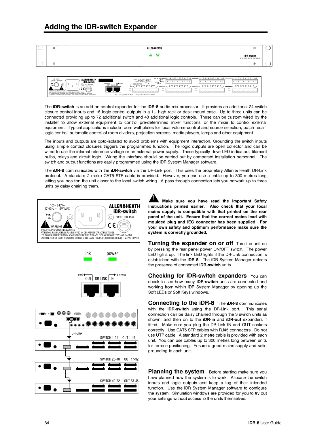
The
The inputs and outputs are
The
100 - 240V~
47-63Hz ~ 15W MAX
FUSE: T500mAL
![]() WARNING
WARNING ![]()
THIS APPARATUS MUST BE EARTHED.
ATTENTION: REMPLACER LE FUSIBLE AVEC UN DES MEMES CARACTERISTIQUES.
FOR CONTINUED PROTECTION AGAINST RISK OF FIRE REPLACE FUSE WITH SAME TYPE AND RATING. CAUTION: RISK OF ELECTRIC SHOCK. DO NOT OPEN. AVIS: RISQUE DE CHOC ELECTRIQUE - NE PAS OUVRIR.
link | power |
next | previous |
OUT |
| |
SWITCH | OUT |
SWITCH
![]() Make sure you have read the Important Safety Instructions printed earlier. Also check that your local mains supply is compatible with that printed on the rear panel of the unit. Ensure that the correct mains lead with moulded plug and IEC connector has been supplied. For your own safety and optimum performance make sure the system is correctly grounded.
Make sure you have read the Important Safety Instructions printed earlier. Also check that your local mains supply is compatible with that printed on the rear panel of the unit. Ensure that the correct mains lead with moulded plug and IEC connector has been supplied. For your own safety and optimum performance make sure the system is correctly grounded.
Turning the expander on or off Turn the unit on
by pressing the rear panel power ON/OFF switch. The power LED lights up. The link LED lights if the
Checking for iDR-switch expanders You can
check to see how many
Connecting to the iDR-8 The iDR-8 communicates
with the
Planning the system Before starting make sure you
SWITCH
have planned how the system is to work. Allocate the switch inputs and logic outputs and keep a log of their intended function. Use the iDR System Manager software to configure the system. Simulation windows are provided for you to try out your settings without access to the units themselves.
34 |