XLR Analogue Inputs and Outputs
IN 1
+
![]() -
-
OUT 1
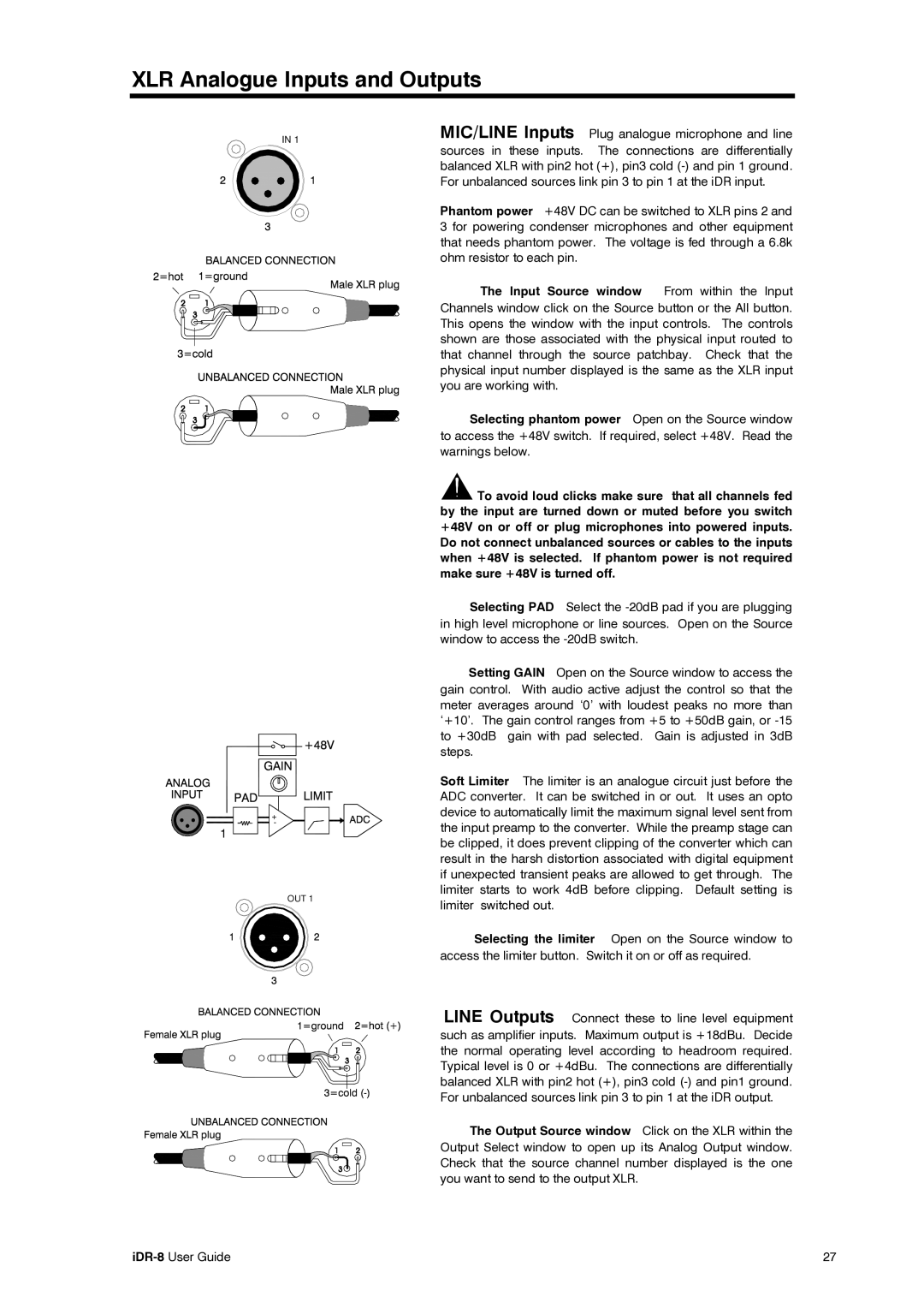
MIC/LINE Inputs Plug analogue microphone and line sources in these inputs. The connections are differentially balanced XLR with pin2 hot (+), pin3 cold
Phantom power +48V DC can be switched to XLR pins 2 and 3 for powering condenser microphones and other equipment that needs phantom power. The voltage is fed through a 6.8k ohm resistor to each pin.
The Input Source window From within the Input
Channels window click on the Source button or the All button. This opens the window with the input controls. The controls shown are those associated with the physical input routed to that channel through the source patchbay. Check that the physical input number displayed is the same as the XLR input you are working with.
Selecting phantom power Open on the Source window to access the +48V switch. If required, select +48V. Read the warnings below.
![]() To avoid loud clicks make sure that all channels fed by the input are turned down or muted before you switch +48V on or off or plug microphones into powered inputs. Do not connect unbalanced sources or cables to the inputs when +48V is selected. If phantom power is not required make sure +48V is turned off.
To avoid loud clicks make sure that all channels fed by the input are turned down or muted before you switch +48V on or off or plug microphones into powered inputs. Do not connect unbalanced sources or cables to the inputs when +48V is selected. If phantom power is not required make sure +48V is turned off.
Selecting PAD Select the
Setting GAIN Open on the Source window to access the gain control. With audio active adjust the control so that the meter averages around ‘0’ with loudest peaks no more than ‘+10’. The gain control ranges from +5 to +50dB gain, or
Soft Limiter The limiter is an analogue circuit just before the ADC converter. It can be switched in or out. It uses an opto device to automatically limit the maximum signal level sent from the input preamp to the converter. While the preamp stage can be clipped, it does prevent clipping of the converter which can result in the harsh distortion associated with digital equipment if unexpected transient peaks are allowed to get through. The limiter starts to work 4dB before clipping. Default setting is limiter switched out.
Selecting the limiter Open on the Source window to access the limiter button. Switch it on or off as required.
LINE Outputs Connect these to line level equipment such as amplifier inputs. Maximum output is +18dBu. Decide the normal operating level according to headroom required. Typical level is 0 or +4dBu. The connections are differentially balanced XLR with pin2 hot (+), pin3 cold
The Output Source window Click on the XLR within the Output Select window to open up its Analog Output window. Check that the source channel number displayed is the one you want to send to the output XLR.
| 27 |