Front Panel Overview
L17 | L18 | L19 | L20 | L21 | L22 | L23 | L24 | L25 | L26 | L27 | L28 | L29 | L30 | L31 |
|
|
|
|
|
|
|
| Allen & Heath |
|
|
|
|
|
|
|
|
|
|
|
|
|
| Wed 13:44:08 |
|
|
|
|
|
|
L1 | L2 | L3 | L4 | L5 | L6 | L7 | L8 | L9 | L10 | L11 | L12 | L13 | L14 | L15 |
S1 | S2 | S3 | S4 | S5 | S6 | S7 | S8 | S9 | S10 | S11 | S12 | S13 | S14 | S15 |
L32
L16
S16
LEVEL TRIM
|
|
| < | scroll |
|
|
|
|
|
| < | > |
|
| |
|
|
|
|
| audio monitor | ||
CODE UPDATE | FRONT/REAR | ext | ESC |
| ENTER | MENU | |
| patch select | ||||||
active | slave | sync | 96k |
|
|
| day & clock |
lock |
|
|
| network setup | |||
|
|
|
|
|
|
| diagnostics |
| RS232 |
|
|
|
| hold for 2 seconds | |
|
|
|
|
|
|
| |
| For connection to PC com port |
|
|
|
|
|
|
lock link power
AUDIO INPUT EXPANDER
lock link power
AUDIO OUTPUT EXPANDER
link power
24 IN 16 OUT SWITCH CONTROLLER
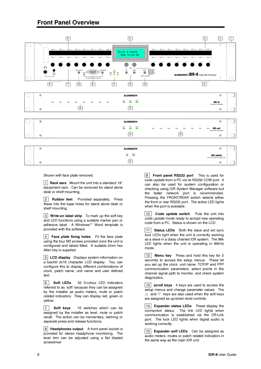
Shown with face plate removed.
1Rack ears Mount the unit into a standard 19” equipment rack. Can be removed for stand alone desk or shelf mounting.
2Rubber feet Provided separately. Press these into the base holes for stand alone desk or shelf mounting.
3
4 Face plate fixing holes Fit the face plate using the four M3 screws provided once the unit is configured and labels fitted. A suitable 2mm hex Allen key is supplied.
5LCD display Displays system information on a backlit 2x16 character LCD display. You can configure this to display different combinations of clock, patch name, unit name and user defined text.
6Soft LEDs 32
7Soft keys 16 switches which can be assigned by the installer as level, mute or patch recall. The action can be momentary, latching or separate press and release functions.
8 Headphones output A front panel socket is provided for stereo headphone monitoring. The level trim can be adjusted using a flat bladed screwdriver
9 Front panel RS232 port This is used for
code update from a PC via its RS232 COM port. It can also be used for system configuration or checking using iDR System Manager software but the faster network port is recommended. Pressing the FRONT/REAR switch selects either the front or rear RS232 port. The active LED lights when the port is available.
10 Code update switch Puts the unit into code update mode ready to accept new operating code from a PC. Status is shown on the LCD.
11Status LEDs Both the slave and ext sync lock LEDs light when the unit is correctly working as a slave in a daisy chained iDR system. The 96k LED lights when the unit is operating in 96kHz mode.
12Menu key Press and hold this key for 2 seconds to access the setup menus. These let you set up the clock, unit name, TCP/IP and PPP communication parameters, select points in the channel signal path to monitor, and check system diagnostics.
13scroll keys 4 keys are used to access the setup menus and change parameter values. The U and V keys are also used when the soft keys are assigned as up/down level controls.
14 Expander status LEDs These display the
connection status. The link LED lights when communication is established via the
15 Expander soft LEDs Can be assigned as audio meters, mutes or patch related indicators in the same way as the main iDR unit.
8 |