Cooper Bussmann Wireless Ethernet & Device Server
Directional Antennas
Directional antennas can be a:
•Yagi antenna with a main beam and orthogonal elements
•Directional radome, which is cylindrical in shape
•Parabolic antenna
A directional antenna provides high gain in the forward direction, but lower gain in other directions. This may be used to compensate for coaxial cable loss for installations with marginal radio path.
Yagi antennas should be installed with the main beam horizontal, pointing in the forward direction. If the Yagi is transmitting to a vertically mounted
Directional radomes should be installed with the central beam horizontal and must be pointed exactly in the direction of transmission to benefit from the gain of the antenna. Parabolic antennas should be mounted as per the manufacturer’s instructions, with the parabolic grid at the “back” and the radiating element pointing in the direction of the transmission.
Ensure that the antenna mounting bracket is well connected to “ground/earth.”
2.3 Power Supply
The
The power requirements of the
| 12Vdc | 24Vdc |
Quiescent | 300mA | 160mA |
TX @100mW | 370mA | 190mA |
TX @ 400mW | 410mA | 210mA |
A Ground Terminal is provided on the back of the module. This Terminal should be connected to the Main Ground point of the installation in order to provide efficient surge protection for the module (refer to the Installation Diagram)
2.4 Serial Connections
RS232 Serial Port
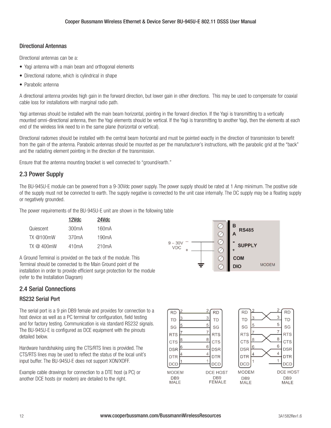
The serial port is a 9 pin DB9 female and provides for connection to a host device as well as a PC terminal for configuration, field testing and for factory testing. Communication is via standard RS232 signals. The
Hardware handshaking using the CTS/RTS lines is provided. The CTS/RTS lines may be used to reflect the status of the local unit’s input buffer. The
Example cable drawings for connection to a DTE host (a PC) or another DCE hosts (or modem) are detailed to the right.
12 | www.cooperbussmann.com/BussmannWirelessResources | 3A1582Rev1.6 |