Cooper Bussmann Wireless Ethernet & Device Server BU-945U-E 802.11 DSSS User Manual
CHAPTER 1 - INTRODUCTION
The BU-945U-E Industrial 802.11 Wireless Ethernet module provide wireless connections between Ethernet devices and/or Ethernet wired networks (LAN’s) and complies with relevant IEEE 802.11 standard.
BU-945U-E 802.11 630mW max power
The BU-945U-E uses a 900 MHz Direct Sequence Spread Spectrum (DSSS) wireless transceiver. There are four bands with each band utilizing different frequencies and bandwidths dependent on the country and their radio regulations. See Section 3.2 “Selecting a Channel” for a more detailed overview.
The BU-945U-E unit also provides two serial connections as well as the Ethernet connections. It is possible to use all three data connections concurrently, allowing the BU-945U-E to act as a Device Server. Wireless connections can be made between serial devices and Ethernet devices. The BU-945U-E provides connection functionality between serial “Modbus RTU” devices and Ethernet “Modbus TCP” devices. Appropriate driver applications will be required in the host devices to handle other protocols.
The BU-945U-E has a standard RJ45 Ethernet connection which will operate at up to 100Mbit/sec. The module will transmit the Ethernet messages on the wireless band at rates between 1 and 54 Mbit/sec & 6 and 54 Mbit/sec depending on model, band, encryption methods, and radio paths.
1.1 Network Topology
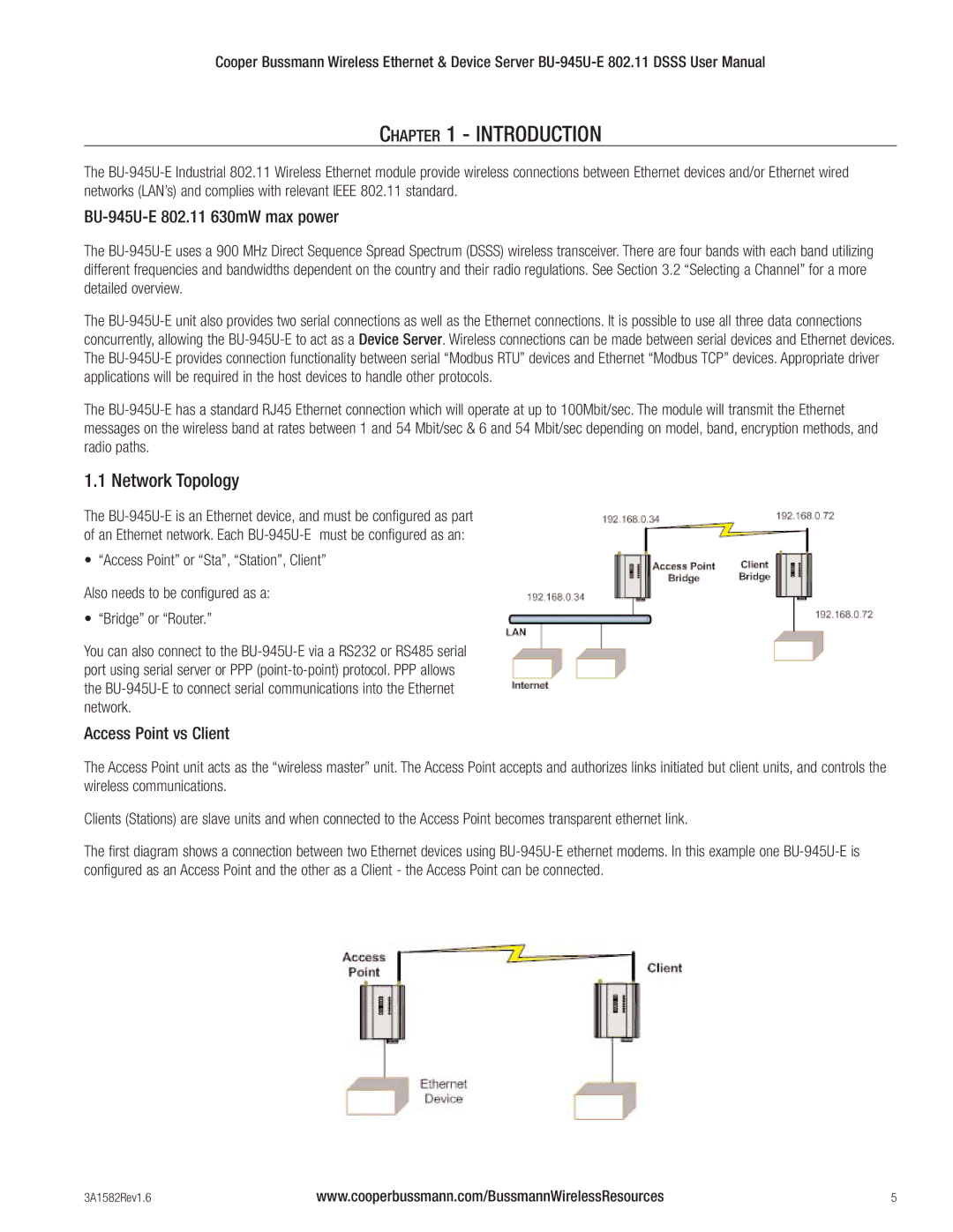
The BU-945U-E is an Ethernet device, and must be configured as part of an Ethernet network. Each BU-945U-E must be configured as an:
• “Access Point” or “Sta”, “Station”, Client”
Also needs to be configured as a:
• “Bridge” or “Router.”
You can also connect to the BU-945U-E via a RS232 or RS485 serial port using serial server or PPP (point-to-point) protocol. PPP allows the BU-945U-E to connect serial communications into the Ethernet network.
Access Point vs Client
The Access Point unit acts as the “wireless master” unit. The Access Point accepts and authorizes links initiated but client units, and controls the wireless communications.
Clients (Stations) are slave units and when connected to the Access Point becomes transparent ethernet link.
The first diagram shows a connection between two Ethernet devices using BU-945U-E ethernet modems. In this example one BU-945U-E is configured as an Access Point and the other as a Client - the Access Point can be connected.