Cooper Bussmann Wireless Ethernet & Device Server
DB9 Connector Pinouts
Pin | Name | Direction | Function |
1 | DCD | Out | Data carrier detect |
2 | RD | Out | Transmit Data – Serial Data Output (from DCE to DTE) |
3 | TD | In | Receive Data – Serial Data Input (from DTE to DCE) |
4 | DTR | In | Data Terminal Ready |
5 | SG | - - | Signal Ground |
6 | DSR | Out | Data Set Ready - always high when unit is powered on. |
7 | RTS | In | Request to Send |
8 | CTS | Out | Clear to send |
9 | RI | - - | Ring indicator |
RS485 Serial Port
The RS485 port provides for communication between the
As the RS485 communication medium is shared, only one of the units on the RS485 cable may send data at any one time. Thus, communication protocols based on the
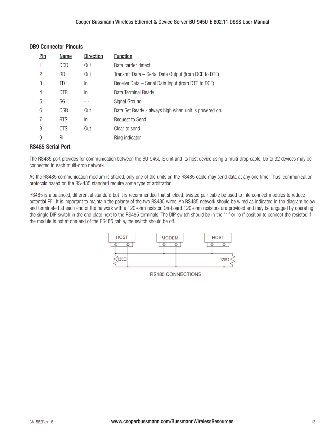
RS485 is a balanced, differential standard but it is recommended that shielded, twisted pair cable be used to interconnect modules to reduce potential RFI. It is important to maintain the polarity of the two RS485 wires. An RS485 network should be wired as indicated in the diagram below and terminated at each end of the network with a
3A1582Rev1.6 | www.cooperbussmann.com/BussmannWirelessResources | 13 |