Cooper Bussmann Wireless Ethernet & Device Server
WDS Connections:
Connection Mode | Specify the connection mode for this link. AP (Downlink) configures the connection as a virtual access point. |
| Sta (Uplink) configures the connection as a virtual client. |
SSID / MAC Address | AP Mode: Specify the SSID that this virtual access point will use. Stations connecting to this virtual access point use |
| this SSID. Sta Mode: Specify the SSID that this virtual station will use when connecting to other access points. |
| |
| for |
Encryption | Select the required Encryption (if any) for this WDS link. |
Encryption Key | Enter the Encryption key (for WEP encryption) or the passphrase (for WPA encryption). For WEP encryption, the |
| encryption key is set as WEP Key 1. For Sta Mode, this must match WEP Key 1 on the Access point this virtual client |
| will connect to. For AP mode, clients must configure their WEP Key 1 to the same value as this key and select the |
| Default WEP Key to be WEP Key 1. |
Router IP | Leave this field blank if this WDS interface is to be bridged with the default wireless interface. Otherwise enter the |
| IP address for this connection that specifies the IP network to which messages are routed. |
Router Subnet | Leave this field blank if this WDS interface is to be bridged with the default wireless interface. Otherwise enter the |
| subnet mask of the network to which messages are routed. |
STP | Applicable to WDS bridged connections only. Select the STP option if you wish to enable the bridge Spanning Tree |
| Protocol on this connection. |
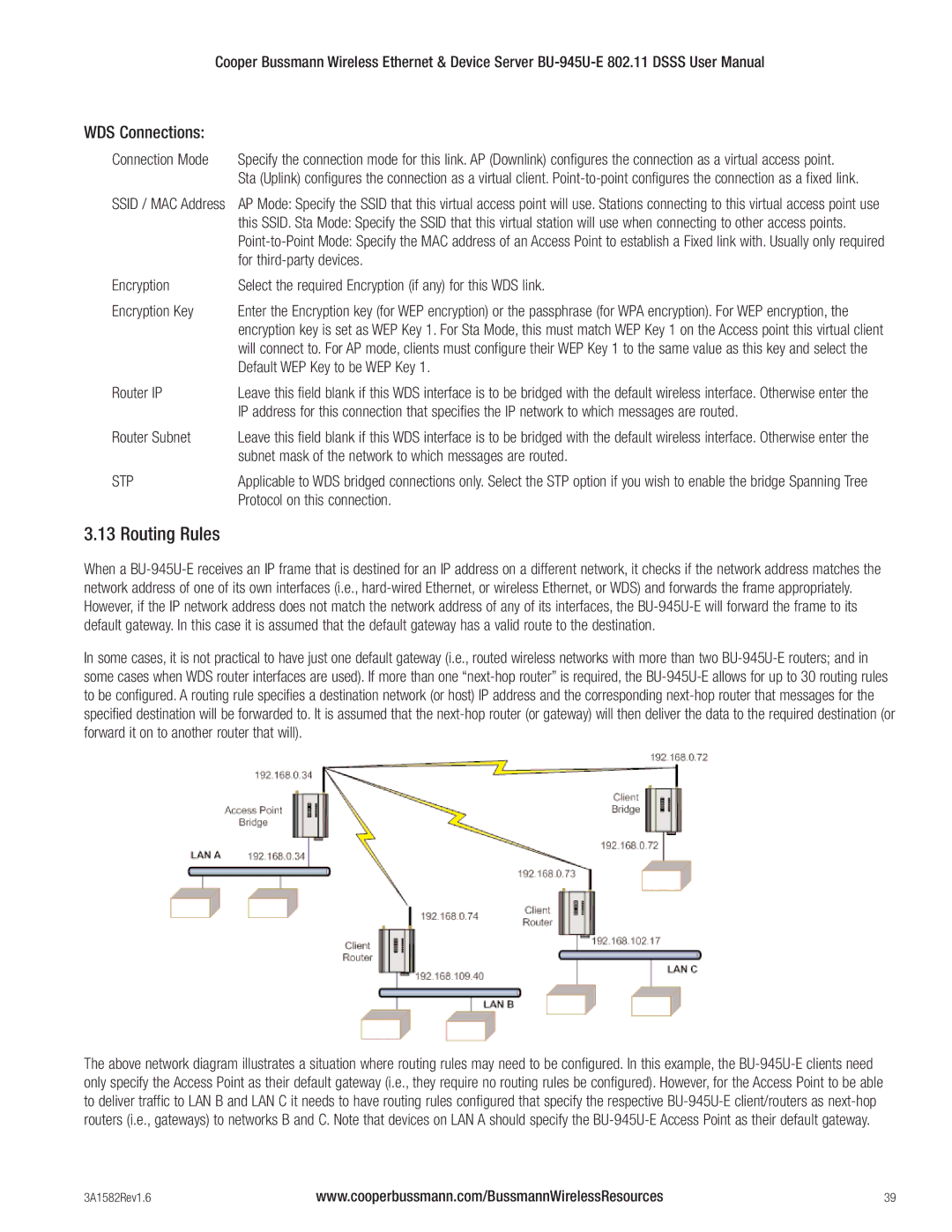
3.13 Routing Rules
When a
In some cases, it is not practical to have just one default gateway (i.e., routed wireless networks with more than two
The above network diagram illustrates a situation where routing rules may need to be configured. In this example, the
3A1582Rev1.6 | www.cooperbussmann.com/BussmannWirelessResources | 39 |