Cooper Bussmann Wireless Ethernet & Device Server
•The second WDS entry above specifies a WDS link from Site B as a virtual Access Point interface and like the WDS link to Site A, we use a different Router IP address (169.254.5.X) than the default interface. Note that this network address is also different to that used for the WDS
link to Site A, so that these separate WDS interfaces are not internally bridged. In addition, the WDS link to unit A, a routing rule is added to direct traffic destined for the network address of unit C (192.168.6.x).
•The third WDS entry above specifies the WDS link to Site D. In the example, Site D is part of the same network structure as Site B; therefore, we wish to have the WDS interface link to Site D bridged with the default interface. Because we don’t specify a router IP address for the third entry the
So, in this example, Site B has a total of three IP addresses: 192.168.5.3 for the default interface; 169.254.0.3 for the WDS link to Site A; and
169.254.5.3 for the WDS link to Site C. Note: We choose to always use the same host address of 3 for unit B on all of its interfaces regardless of the network address.
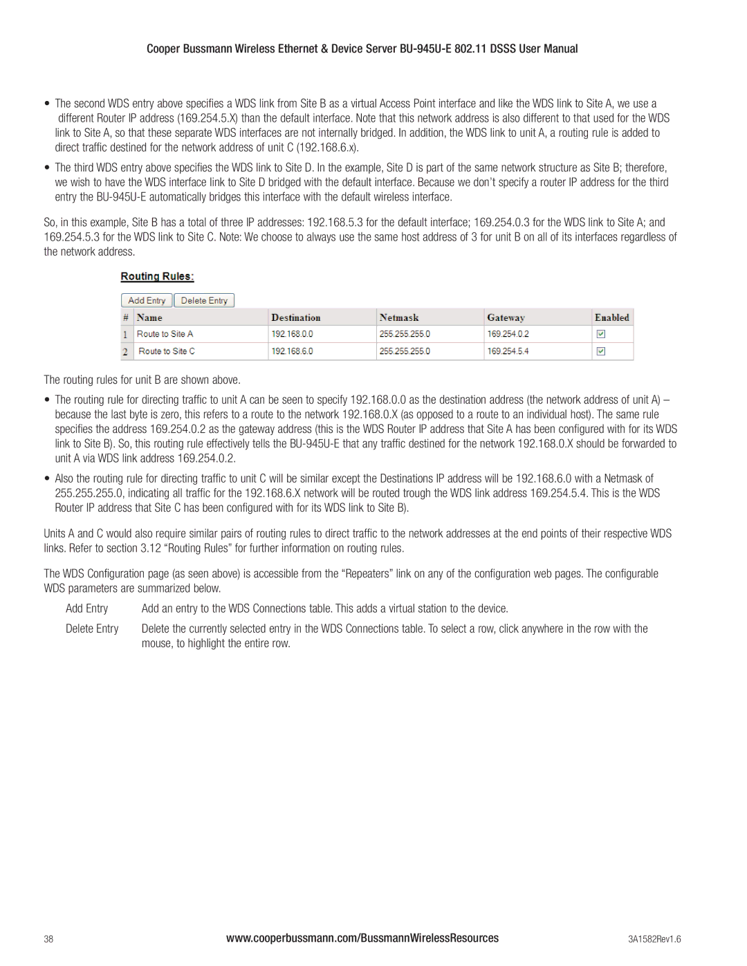
The routing rules for unit B are shown above.
•The routing rule for directing traffic to unit A can be seen to specify 192.168.0.0 as the destination address (the network address of unit A) – because the last byte is zero, this refers to a route to the network 192.168.0.X (as opposed to a route to an individual host). The same rule specifies the address 169.254.0.2 as the gateway address (this is the WDS Router IP address that Site A has been configured with for its WDS link to Site B). So, this routing rule effectively tells the
•Also the routing rule for directing traffic to unit C will be similar except the Destinations IP address will be 192.168.6.0 with a Netmask of 255.255.255.0, indicating all traffic for the 192.168.6.X network will be routed trough the WDS link address 169.254.5.4. This is the WDS Router IP address that Site C has been configured with for its WDS link to Site B).
Units A and C would also require similar pairs of routing rules to direct traffic to the network addresses at the end points of their respective WDS links. Refer to section 3.12 “Routing Rules” for further information on routing rules.
The WDS Configuration page (as seen above) is accessible from the “Repeaters” link on any of the configuration web pages. The configurable WDS parameters are summarized below.
Add Entry | Add an entry to the WDS Connections table. This adds a virtual station to the device. |
Delete Entry | Delete the currently selected entry in the WDS Connections table. To select a row, click anywhere in the row with the |
| mouse, to highlight the entire row. |
38 | www.cooperbussmann.com/BussmannWirelessResources | 3A1582Rev1.6 |