Cooper Bussmann Wireless Ethernet & Device Server
Access Point Configuration
•Connect straight through Ethernet cable between PC and
•Ensure configuration PC and
•Set DIP switch to SETUP
•Power up unit, and wait for LINK led to cease flashing
•Adjust PC network settings
•Set Configuration PC network card with network setting of IP address 192.168.0.1, netmask 255.255.255.0
•Open configuration webpage with Internet Explorer at address 192.168.0.1XX/
•When prompted for password, enter default username “user” and password “user”
•Enter “Network,” and select Operating Mode as Access Point
•Device Mode should be set to Router
•Set the Gateway IP address to 192.168.0.1
•Set the Ethernet IP address to 192.168.0.200, network mask 255.255.255.0
•Set the Wireless IP address to 169.254.102.54, network mask 255.255.255.0
•Select the Radio Encryption required, and enter encryption keys or passphrase if necessary
•Set DIP switch to RUN
•Click on button Save to Flash and Reset. Webpage will display that message indicating details are being written to flash. Wait for
Client Configuration
Perform the same configuration steps as the Access Point configuration with the following differences:
•Enter “Network,” and select Operating Mode as Client
•Device Mode should be set to Bridge
•Set the Gateway IP address to 169.254.102.54
•Set the Ethernet IP address to 169.254.102.53, network mask 255.255.255.0
•Set the Wireless IP address to 169.254.102.53, network mask 255.255.255.0
•Click on button Save to Flash and Reset. Webpage will display that message indicating details are being written to flash. Wait for
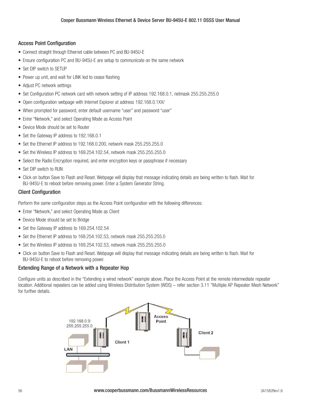
Extending Range of a Network with a Repeater Hop
Configure units as described in the “Extending a wired network” example above. Place the Access Point at the remote intermediate repeater location. Additional repeaters can be added using Wireless Distribution System (WDS) – refer section 3.11 ”Multiple AP Repeater Mesh Network” for further details.
56 | www.cooperbussmann.com/BussmannWirelessResources | 3A1582Rev1.6 |