Cooper Bussmann Wireless Ethernet & Device Server
An alternative to adding routing rules to the
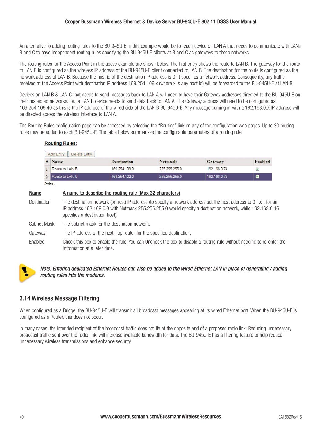
The routing rules for the Access Point in the above example are shown below. The first entry shows the route to LAN B. The gateway for the route to LAN B is configured as the wireless IP address of the
Devices on LAN B & LAN C that needs to send messages back to LAN A will need to have their Gateway addresses directed to the
The Routing Rules configuration page can be accessed by selecting the “Routing” link on any of the configuration web pages. Up to 30 routing rules may be added to each
Name | A name to describe the routing rule (Max 32 characters) |
Destination | The destination network (or host) IP address (to specify a network address set the host address to 0. i.e., for an |
| IP address 192.168.0.0 with Netmask 255.255.255.0 would specify a destination network, while 192.168.0.16 |
| specifies a destination host). |
Subnet Mask | The subnet mask for the destination network. |
Gateway | The IP address of the |
Enabled | Check this box to enable the rule. You can Uncheck the box to disable a routing rule without needing to |
| information at a later time. |
Note: Entering dedicated Ethernet Routes can also be added to the wired Ethernet LAN in place of generating / adding routing rules into the modems.
3.14 Wireless Message Filtering
When configured as a Bridge, the
In many cases, the intended recipient of the broadcast traffic does not lie at the opposite end of a proposed radio link. Reducing unnecessary broadcast traffic sent over the radio link, will increase available bandwidth for data. The
40 | www.cooperbussmann.com/BussmannWirelessResources | 3A1582Rev1.6 |