Cooper Bussmann Wireless Ethernet & Device Server BU-945U-E 802.11 DSSS User Manual
3.17 Modbus I/O Transfer
The BU-945U-E provides Modbus TCP Client and Modbus TCP Server functionality for I/O transfer. 5000 x 16bit general purpose registers are provided for Modbus (including the onboard Digital Input/Output) and are shared for both Client and Server. Modbus TCP Client (Master) and Modbus TCP Server (Slave) are both supported simultaneously, and when combined with the built in Modbus TCP to RTU Gateway the BU-945U-E can transfer I/O to/from almost any combination of Modbus TCP or RTU devices.
The layout of the BU-945U-E I/O Registers is summarized in the table below. Each register is internally saved as a 16 unsigned integer value. A Modbus transaction may access the entire 16 bit value of any register, or alternatively the most significant bit of a register may be accessed as a discrete value. The main use for the general purpose I/O registers is for intermediate storage, i.e., when transferring I/O from one Modbus Slave device to another. Also provided is the status of the onboard digital I/O, as well as the status of the wireless link and any serial or
TCP connections.
An inverted status of registers 4300 – 4307 are also available and can be found at register locations 4370 – 4377.
The status register will contain the value FFFF (hex) for ON and 0000 (hex) for OFF.
Registers | Purpose |
1 – 4299 | General purpose I/O registers (read/write) |
4300 | On-board Digital Input value (read only) |
4301 | Link Status (read only) |
4302 | Serial Gateway (RS232) Connection Status |
4303 | Serial Gateway (RS485) Connection Status |
4304 | TCP-RTU (RS232) Connection Status |
4305 | TCP-RTU (RS485) Connection Status |
4306 | TCP-RTU Modbus Server Connection Status |
4307 | Multicast Pipe Connection Status |
4310 | TCP-RTU (RS232) Number of Connections |
4311 | TCP-RTU (RS485) Number of Connections |
4312 | TCP-RTU Modbus Server Number of Connections |
4320 | On-board Digital Output value (read/write) |
4378-4999 | Reserved for future use |
Modbus TCP Client (Master) enables the BU-945U-E to connect to one or more Modbus TCP Servers (Slaves).
All Modbus Master messages are directed to/from the onboard I/O registers depending on configuration (described below). The Modbus TCP Client may also poll Modbus RTU (i.e., serial) devices connected to either the local serial port or a remote BU-945U-E serial port by enabling the Modbus TCP to RTU gateway at the corresponding serial port (see section 3.14 “Serial Port Configuration”).
Modbus TCP Client functionality allows connections to a maximum of 25 different Modbus TCP Servers.
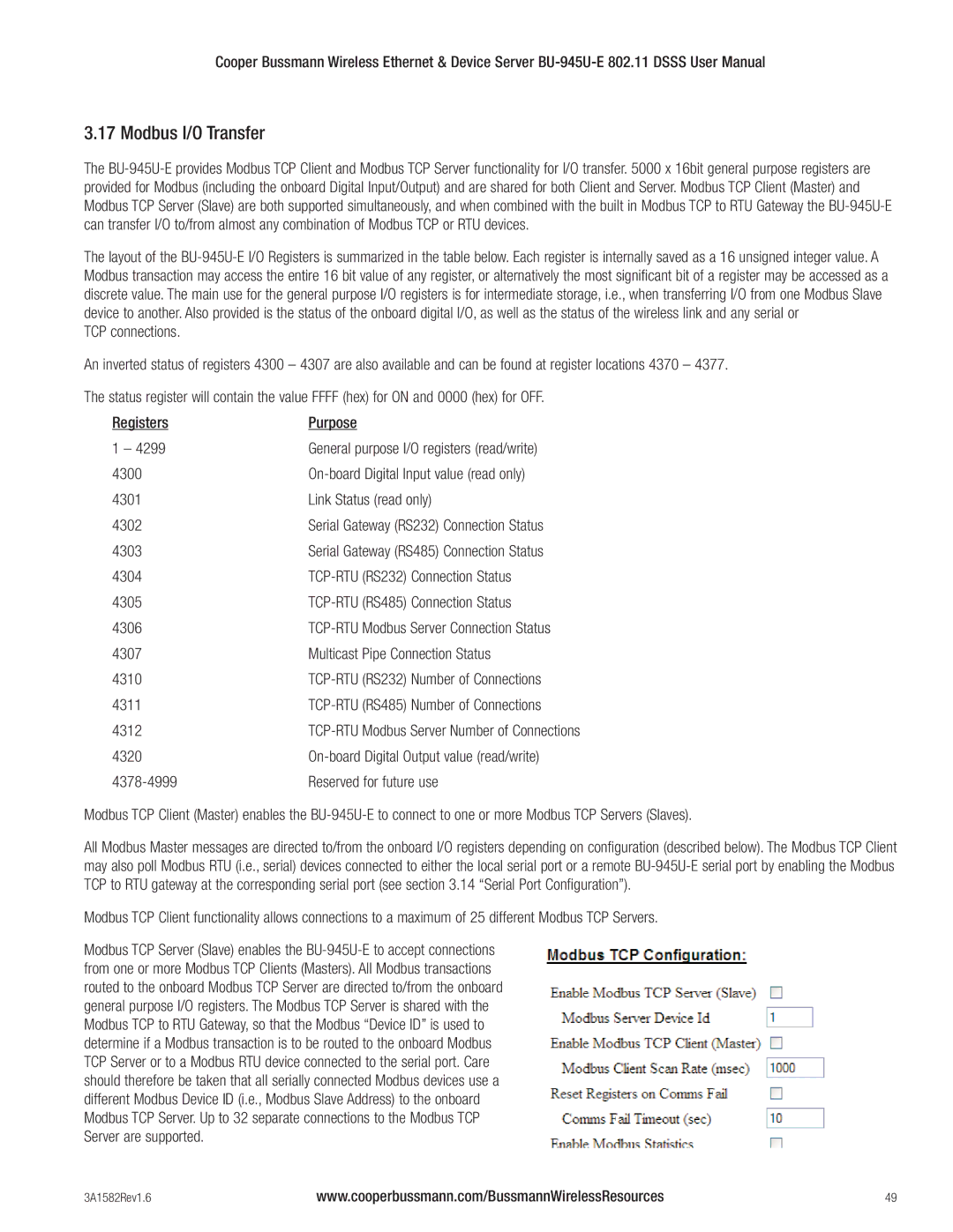
Modbus TCP Server (Slave) enables the BU-945U-E to accept connections from one or more Modbus TCP Clients (Masters). All Modbus transactions routed to the onboard Modbus TCP Server are directed to/from the onboard general purpose I/O registers. The Modbus TCP Server is shared with the Modbus TCP to RTU Gateway, so that the Modbus “Device ID” is used to determine if a Modbus transaction is to be routed to the onboard Modbus TCP Server or to a Modbus RTU device connected to the serial port. Care should therefore be taken that all serially connected Modbus devices use a different Modbus Device ID (i.e., Modbus Slave Address) to the onboard Modbus TCP Server. Up to 32 separate connections to the Modbus TCP Server are supported.