Cooper Bussmann Wireless Ethernet & Device Server
Modbus RTU (serial) Master functionality is achieved by combining the Modbus TCP Client (Master) and Modbus TCP to RTU Gateway. Simply specify a Modbus TCP Client (Master) connection to a Modbus TCP Server where the server is the address of any
The
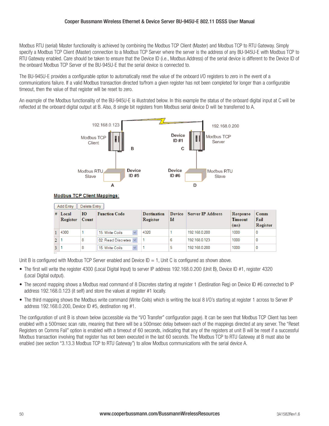
An example of the Modbus functionality of the
Unit B is configured with Modbus TCP Server enabled and Device ID = 1, Unit C is configured as shown above.
•The first will write the register 4300 (Local Digital Input) to server IP address 192.168.0.200 (Unit B), Device ID #1, register 4320 (Local Digital output).
•The second mapping shows a Modbus read command of 8 Discretes starting at register 1 (Destination Reg) on Device ID #6 connected to IP address 192.168.0.123 (it self) and store the values at register #1 locally.
•The third mapping shows the Modbus write command (Write Coils) which is writing the local 8 I/O’s starting at register 1 across to Server IP address 192.168.0.200, Device ID #5, destination reg #1.
The configuration of unit B is shown below (accessible via the “I/O Transfer” configuration page). It can be seen that Modbus TCP Client has been enabled with a 500msec scan rate, meaning that there will be a 500msec delay between each of the mappings directed at any server. The “Reset Registers on Comms Fail” option is enabled with a timeout of 60 seconds, indicating that any of the registers at unit B will be reset if a successful Modbus transaction involving that register has not been executed in the last 60 seconds. The Modbus TCP to RTU Gateway at B must also be enabled (see section “3.13.3 Modbus TCP to RTU Gateway”) to allow Modbus communications with the serial device A.
50 | www.cooperbussmann.com/BussmannWirelessResources | 3A1582Rev1.6 |