Cooper Bussmann Wireless Ethernet & Device Server
Example – WDS Routed Network
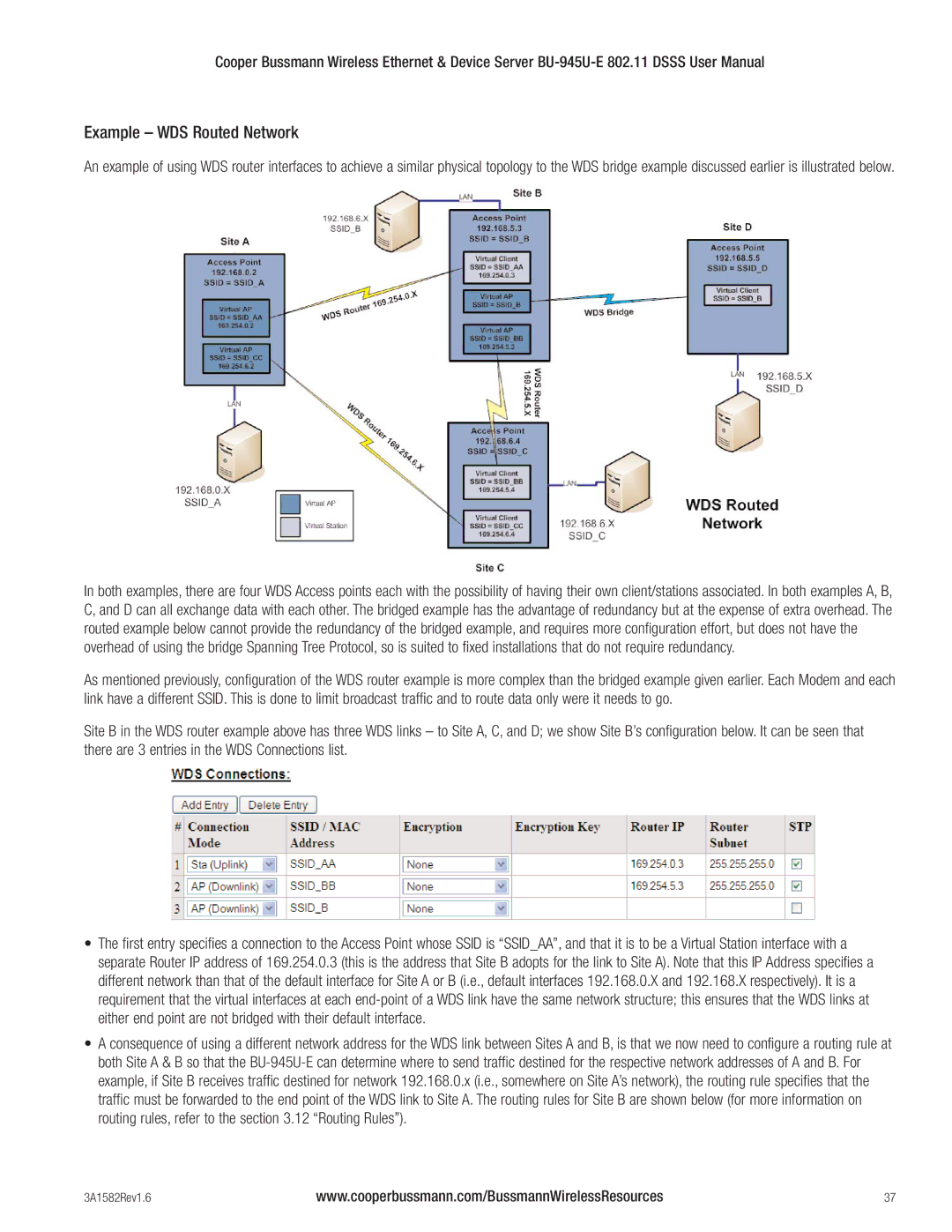
An example of using WDS router interfaces to achieve a similar physical topology to the WDS bridge example discussed earlier is illustrated below.
In both examples, there are four WDS Access points each with the possibility of having their own client/stations associated. In both examples A, B, C, and D can all exchange data with each other. The bridged example has the advantage of redundancy but at the expense of extra overhead. The routed example below cannot provide the redundancy of the bridged example, and requires more configuration effort, but does not have the overhead of using the bridge Spanning Tree Protocol, so is suited to fixed installations that do not require redundancy.
As mentioned previously, configuration of the WDS router example is more complex than the bridged example given earlier. Each Modem and each link have a different SSID. This is done to limit broadcast traffic and to route data only were it needs to go.
Site B in the WDS router example above has three WDS links – to Site A, C, and D; we show Site B’s configuration below. It can be seen that there are 3 entries in the WDS Connections list.
•The first entry specifies a connection to the Access Point whose SSID is “SSID_AA”, and that it is to be a Virtual Station interface with a separate Router IP address of 169.254.0.3 (this is the address that Site B adopts for the link to Site A). Note that this IP Address specifies a different network than that of the default interface for Site A or B (i.e., default interfaces 192.168.0.X and 192.168.X respectively). It is a requirement that the virtual interfaces at each
•A consequence of using a different network address for the WDS link between Sites A and B, is that we now need to configure a routing rule at both Site A & B so that the
3A1582Rev1.6 | www.cooperbussmann.com/BussmannWirelessResources | 37 |
