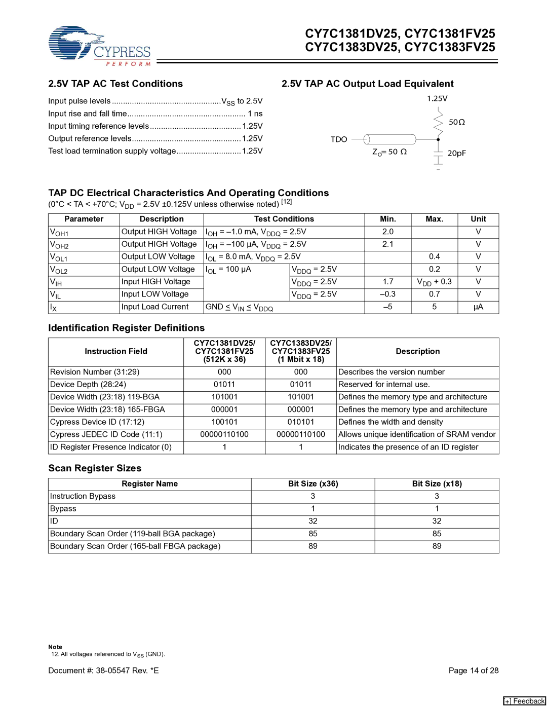
CY7C1383DV25, CY7C1381FV25, CY7C1381DV25, CY7C1383FV25 specifications
Cypress Semiconductor's family of static random-access memory (SRAM) chips, including the CY7C1381FV25, CY7C1383DV25, CY7C1381DV25, and CY7C1383FV25, are designed for high-performance applications that require fast access times and low power consumption. These devices are often found in applications such as networking, telecommunications, and industrial control systems, where speed and reliability are paramount.The CY7C1381FV25 and CY7C1381DV25 are single-port SRAMs, while the CY7C1383FV25 and CY7C1383DV25 are dual-port versions that allow for simultaneous read and write operations from two different controllers. This feature significantly enhances data throughput, making these devices ideal for high-bandwidth applications. The devices support asynchronous read and write operations, ensuring immediate data accessibility with minimal latency.
One of the key features of these SRAM chips is their fast access times, with read and write cycles as short as 10 nanoseconds. This speed makes them suitable for cache memory applications, where performance is critical. Furthermore, the devices are built on Cypress's advanced process technology, which enables them to achieve high density and low power consumption, ideal for battery-operated devices and systems where energy efficiency is crucial.
The power consumption characteristics also highlight their effectiveness in various applications. The active power consumption can be as low as 80mA, depending on the operation conditions, and the devices offer low standby power, further enhancing their suitability for low-power applications. Additionally, these chips incorporate power-saving features like sleep mode, allowing designers to minimize energy consumption in idle states.
In terms of reliability, Cypress employs rigorous quality control measures, ensuring that the CY7C1381FV25, CY7C1383DV25, CY7C1381DV25, and CY7C1383FV25 meet stringent industry standards. They also feature an extended temperature range, which is vital for industrial applications that may experience harsh environmental conditions.
Overall, the CY7C1381FV25, CY7C1383DV25, CY7C1381DV25, and CY7C1383FV25 SRAM chips are versatile, high-performance memory solutions. Their combination of fast access times, low power consumption, and reliability makes them an excellent choice for engineers and developers looking to implement high-speed memory in a variety of applications. Whether for a communication device or a sophisticated industrial control system, these Cypress SRAMs stand out in the market for their performance and efficiency.

