CY7C1381DV25, CY7C1381FV25

CY7C1383DV25, CY7C1383FV25

Pin Definitions


Name

IO


Description


A0, A1, A

Input-

Address inputs used to select one of the address locations. Sampled at the rising edge


Synchronous

of the CLK if ADSP or

ADSC

is active LOW, and CE

1

, CE

2

, and CE [2] are sampled active.


A[1:0] feed the 2-bit counter.


3


A,


B

Input-

Byte write select inputs, active LOW. Qualified with


to conduct byte writes to the


BW

BW

BWE


BWC, BWD

Synchronous

SRAM. Sampled on the rising edge of CLK.


Input-

Global write enable input, active LOW. When asserted LOW on the rising edge of CLK, a


GW


Synchronous

global write is conducted (all bytes are written, regardless of the values on BW[A:D] and BWE).


CLK

Input-

Clock input. Used to capture all synchronous inputs to the device. Also used to increment


Clock

the burst counter when ADV is asserted LOW, during a burst operation.


1


Input-

Chip enable 1 input, active LOW. Sampled on the rising edge of CLK. Used in conjunction


CE


Synchronous

with CE2 and


3 [2] to select or deselect the device. ADSP is ignored if CE1 is HIGH. CE1


CE


is sampled only when a new external address is loaded.


CE2

Input-

Chip enable 2 input, active HIGH. Sampled on the rising edge of CLK. Used in conjunction


Synchronous

with CE


and


[2] to select or deselect the device. CE


is sampled only when a new


1

CE

3


2


external address is loaded.


3 [2]

Input-

Chip enable 3 input, active LOW. Sampled on the rising edge of CLK. Used in conjunction


CE


Synchronous

with CE1 and CE2 to select or deselect the device. CE3 is sampled only when a new external


address is loaded.


Input-

Output enable, asynchronous input, active LOW. Controls the direction of the IO pins.


OE


Asynchronous

When LOW, the IO pins behave as outputs. When deasserted HIGH, IO pins are tri-stated,


and act as input data pins. OE is masked during the first clock of a read cycle when emerging


from a deselected state.


Input-

Advance input signal. Sampled on the rising edge of CLK. When asserted, it automatically


ADV


Synchronous

increments the address in a burst cycle.


Input-

Address strobe from processor, sampled on the rising edge of CLK, active LOW. When


ADSP


Synchronous

asserted LOW, addresses presented to the device are captured in the address registers.


A[1:0] are also loaded into the burst counter. When ADSP and ADSC are both asserted, only


ADSP is recognized. ASDP is ignored when CE1 is deasserted HIGH.


Input-

Address strobe from controller, sampled on the rising edge of CLK, active LOW. When


ADSC


Synchronous

asserted LOW, addresses presented to the device are captured in the address registers.


A[1:0] are also loaded into the burst counter. When ADSP and ADSC are both asserted, only


ADSP is recognized.


Input-

Byte write enable input, active LOW. Sampled on the rising edge of CLK. This signal must


BWE


Synchronous

be asserted LOW to conduct a byte write.


ZZ

Input-

ZZ sleep input. This active HIGH input places the device in a non-time critical sleep


Asynchronous

condition with data integrity preserved. For normal operation, this pin has to be LOW or left


floating. ZZ pin has an internal pull down.


DQs

IO-

Bidirectional data IO lines. As inputs, they feed into an on-chip data register that is triggered


Synchronous

by the rising edge of CLK. As outputs, they deliver the data contained in the memory location


specified by the addresses presented during the previous clock rise of the read cycle. The


direction of the pins is controlled by OE. When OE is asserted LOW, the pins behave as


outputs. When HIGH, DQs and DQPX are placed in a tri-state condition.The outputs are


automatically tri-stated during the data portion of a write sequence, during the first clock


when emerging from a deselected state, and when the device is deselected, regardless of


the state of OE.


DQPX

IO-

Bidirectional data parity IO lines. Functionally, these signals are identical to DQs. During


Synchronous

write sequences, DQPX is controlled by BWX correspondingly.

Document #: 38-05547 Rev. *E


Page 6 of 28

[+] Feedback

Page 6
Image 6
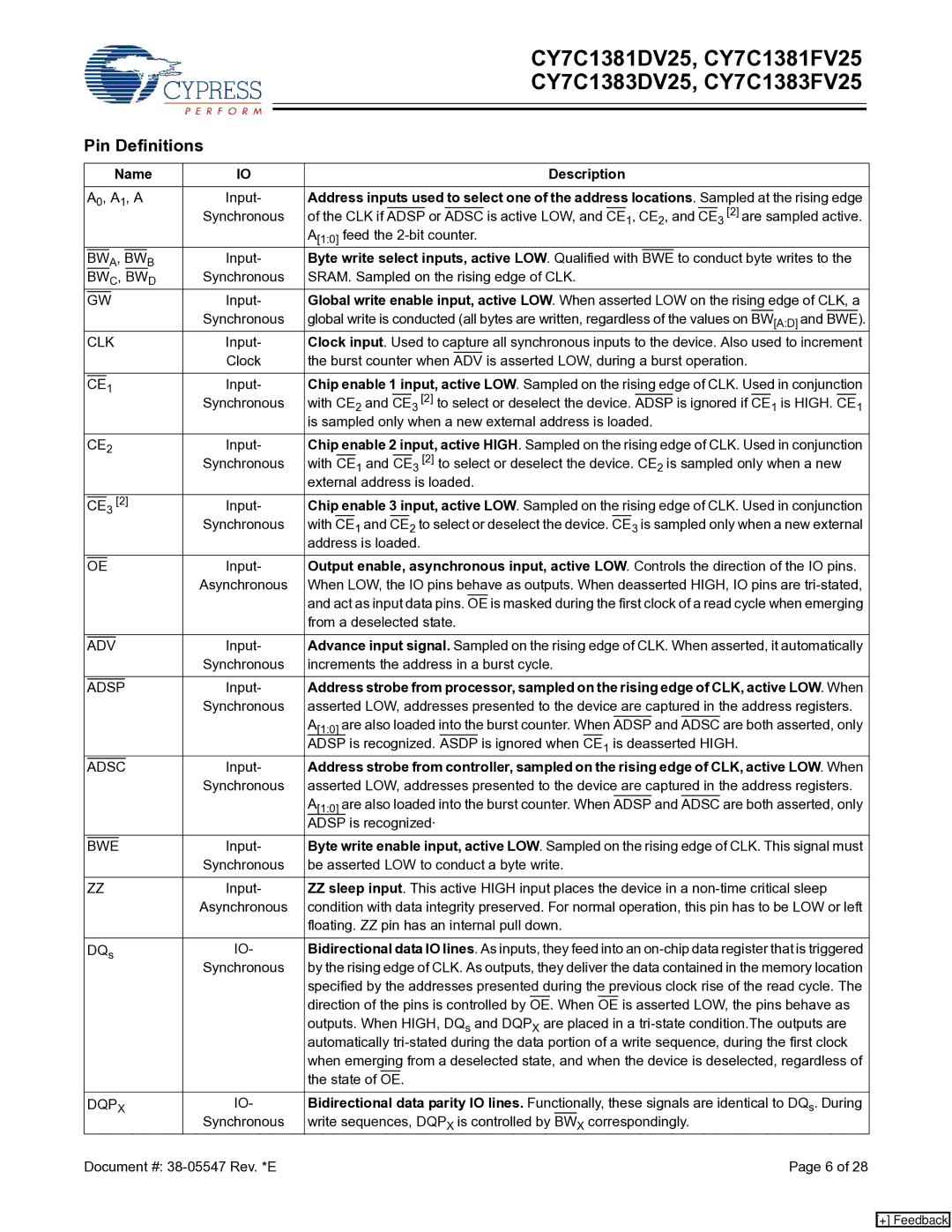
Cypress CY7C1381DV25, CY7C1383DV25 Pin Definitions, Name Description, Byte write select inputs, active LOW. Qualified with

CY7C1383DV25, CY7C1381FV25, CY7C1381DV25, CY7C1383FV25 specifications

Cypress Semiconductor's family of static random-access memory (SRAM) chips, including the CY7C1381FV25, CY7C1383DV25, CY7C1381DV25, and CY7C1383FV25, are designed for high-performance applications that require fast access times and low power consumption. These devices are often found in applications such as networking, telecommunications, and industrial control systems, where speed and reliability are paramount.

The CY7C1381FV25 and CY7C1381DV25 are single-port SRAMs, while the CY7C1383FV25 and CY7C1383DV25 are dual-port versions that allow for simultaneous read and write operations from two different controllers. This feature significantly enhances data throughput, making these devices ideal for high-bandwidth applications. The devices support asynchronous read and write operations, ensuring immediate data accessibility with minimal latency.

One of the key features of these SRAM chips is their fast access times, with read and write cycles as short as 10 nanoseconds. This speed makes them suitable for cache memory applications, where performance is critical. Furthermore, the devices are built on Cypress's advanced process technology, which enables them to achieve high density and low power consumption, ideal for battery-operated devices and systems where energy efficiency is crucial.

The power consumption characteristics also highlight their effectiveness in various applications. The active power consumption can be as low as 80mA, depending on the operation conditions, and the devices offer low standby power, further enhancing their suitability for low-power applications. Additionally, these chips incorporate power-saving features like sleep mode, allowing designers to minimize energy consumption in idle states.

In terms of reliability, Cypress employs rigorous quality control measures, ensuring that the CY7C1381FV25, CY7C1383DV25, CY7C1381DV25, and CY7C1383FV25 meet stringent industry standards. They also feature an extended temperature range, which is vital for industrial applications that may experience harsh environmental conditions.

Overall, the CY7C1381FV25, CY7C1383DV25, CY7C1381DV25, and CY7C1383FV25 SRAM chips are versatile, high-performance memory solutions. Their combination of fast access times, low power consumption, and reliability makes them an excellent choice for engineers and developers looking to implement high-speed memory in a variety of applications. Whether for a communication device or a sophisticated industrial control system, these Cypress SRAMs stand out in the market for their performance and efficiency.