Blade n and Blade (n + 8) |
|
| I/O Module |
|
NOTE: n denotes a |
|
|
|
|
B1 | C1 | C2 | B2 | |
variable value from 1 |
|
|
|
|
to 8. |
|
|
|
|
|
|
|
|
|
Mezz_FAB_C_Blade n |
|
| Port(n+24) |
|
+8_Port4 |
|
|
|
|
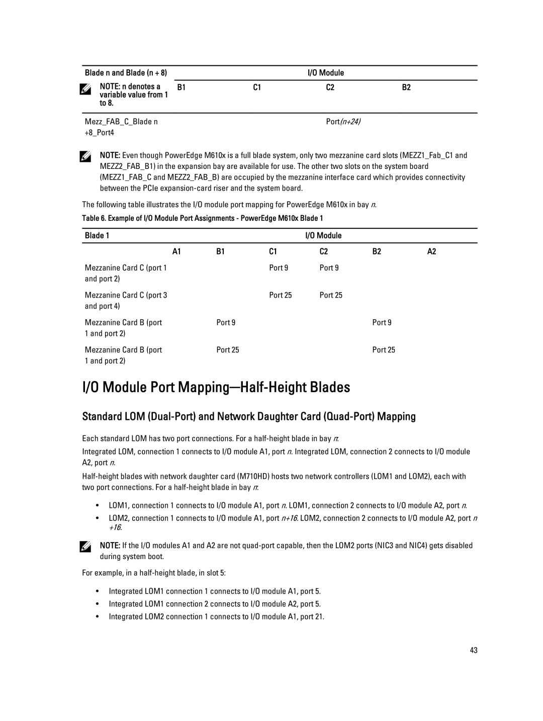
NOTE: Even though PowerEdge M610x is a full blade system, only two mezzanine card slots (MEZZ1_Fab_C1 and MEZZ2_FAB_B1) in the expansion bay are available for use. The other two slots on the system board (MEZZ1_FAB_C and MEZZ2_FAB_B) are occupied by the mezzanine interface card which provides connectivity between the PCIe
The following table illustrates the I/O module port mapping for PowerEdge M610x in bay n.
Table 6. Example of I/O Module Port Assignments - PowerEdge M610x Blade 1
Blade 1 |
|
| I/O Module |
|
|
|
|
|
|
|
|
A1 | B1 | C1 | C2 | B2 | A2 |
Mezzanine Card C (port 1 |
| Port 9 | Port 9 |
|
|
and port 2) |
|
|
|
|
|
Mezzanine Card C (port 3 |
| Port 25 | Port 25 |
|
|
and port 4) |
|
|
|
|
|
Mezzanine Card B (port | Port 9 |
|
| Port 9 |
|
1 and port 2) |
|
|
|
|
|
Mezzanine Card B (port | Port 25 |
|
| Port 25 |
|
1 and port 2) |
|
|
|
|
|
I/O Module Port Mapping─Half-Height Blades
Standard LOM
Each standard LOM has two port connections. For a
Integrated LOM, connection 1 connects to I/O module A1, port n. Integrated LOM, connection 2 connects to I/O module A2, port n.
•LOM1, connection 1 connects to I/O module A1, port n. LOM1, connection 2 connects to I/O module A2, port n.
•LOM2, connection 1 connects to I/O module A1, port n+16. LOM2, connection 2 connects to I/O module A2, port n +16.
NOTE: If the I/O modules A1 and A2 are not
For example, in a
•Integrated LOM1 connection 1 connects to I/O module A1, port 5.
•Integrated LOM1 connection 2 connects to I/O module A2, port 5.
•Integrated LOM2 connection 1 connects to I/O module A1, port 21.
43
