User’s Guide
W. d e l l . c o m s u p p o r t . d e l l . c o m
Abbreviations and Acronyms
Contents
Software Installation and Configuration
Disabling a Forgotten Password
Additional System Setup Options
LegacySelect Technology Control
101
Installing an AGP Graphics Card
100
102
Serial or Parallel Device Problems 164
Installing a Floppy Drive and Reattaching Cables 126
Using the Dell OptiPlex ResourceCD 159
119
When to Use the Dell Diagnostics 181
Repairing a Dropped or Damaged Computer 177
Resetting a Damaged System Board 180
Interrupt Assignment Conflicts 202 Contents
209
Returning Items for Warranty Repair or Credit 209
206
210
Safety First-For You and Your Computer
Electrostatic Discharge
Ergonomic Computing Habits
Page
W . d e l l . c o m s u p p o r t . d e l l . c o m
About Your Computer
Resources Contents Using the Resource
Finding Information and Assistance
Resources Contents Using the Resource
Latest drivers for your computer. If you reinstall your
For the devices shipped with your computer
Go to http//premiersupport.dell.com
Front Panel
A l l Fo r m Fa c t o r C o m p u t e r
A l l D e s k t o p C o m p u t e r
A l l M i n i -To w e r C o m p u t e r
Front Panel Door
Speaker/Headphone Connector
Power Button
Po w e r B u t t o n Fun c t i o n s f o r
Power Light
Action Results Computer Computer Turned Off Turned On
Floppy Drive Access Light
Hard Drive Access Light
Back Panel
PCI slots AC adapter
AGP slot
Connecting Devices
M p u t e r s
USB Connectors
Parallel Connector
Mouse Connector
Integrated Network Adapter Connector
Line-In Jack
Serial Connectors
Keyboard Connector
Line-Out Jack
Access points are color Coded green
Inside Your Computer
A l l D e s k t o p C o m p u t e r
A l l M i n i -To w e r C o m p u t e r
Bl e C o l o r s
System Board Components
21 20 19 18 About Your Computer
About Your Computer
Connector or Socket Description
S t e m B o a r d L a b e l s
Advanced Features
Manageability
Advanced Features
LegacySelect Technology Control
Dell OpenManage IT Assistant
Security
Dell OpenManage Client Instrumentation
Chassis Intrusion Detection
Option settings
Padlock Ring and Security Cable Slot
Password Protection
System Password
Assigning a System Password
Using Your System Password
Setup Password
Deleting or Changing an Existing System Password
Assigning a Setup Password
Operating Your Computer With a Setup Password Enabled
Deleting or Changing an Existing Setup Password
Disabling a Forgotten Password
Open the computer cover
Computer Settings
Entering System Setup
System Setup Screens
S t e m S e t up N a v i g a t i o n Ke y s
Keys Action
Spacebar or
Changing the Boot Sequence During System Setup
Changing the Boot Sequence in System Setup
Additional System Setup Options
Default for Auto Power On is Disabled
Inch, 1.44 MB Not Installed
Advanced Features
Advanced Features
Primary Drive n and Secondary Drive n
If You Have a Problem
Off
Jumper Settings
Jumper Setting Description
Software Installation Configuration
Installing Upgrades
Installing Upgrades
Computer Cover
Opening the Computer Cover
A l l Fo r m Fa c t o r C o m p u t e r
Installing Upgrades
Closing the Computer Cover
Expansion Cards
Installing an Expansion Card
Open the computer cover
A l l Fo r m Fa c t o r C o m p u t e r
O m
A l l M i n i -To w e r C o m p u t e r
ALERT! Cover was previously removed
Removing an Expansion Card
ALERT! Cover was previously removed
Installing an AGP Graphics Card
Hinged lever Indented tab
Installing Upgrades
Removing an AGP Card
Expansion Card Cage Small Desktop Computer Only
Removing the Expansion-Card Cage
Replacing the Expansion-Card Cage
Pa n s i o n C a r d C a ge Re p l a c e m e n t
Installing a Tapi Device
Tapi
Installing a Tapi Sound Card
Installing DIMMs
Memory
M M Installation
You will need to reset the chassis intrusion detector
Removing DIMMs
Procedure
Microprocessor
On the small mini-tower computer, lift up the airflow shroud
Removing the Heat Sink or Heat Sink/Blower Assembly
Installing Upgrades
Removing the Microprocessor
Installing the Microprocessor
Release lever Microprocessor ZIF socket
C r o pr o c e s s o r Installation
Replacing the Heat Sink or Heat Sink/Blower Assembly
Front Panel Inserts
Installing Upgrades
A l l D e s k t o p C o m p u t e r
Removing Front Panel Inserts-Small Mini-Tower Computer
Replacing Front Panel Inserts
100 Installing Upgrades
Internal Drives
Installing Upgrades 101
102 Installing Upgrades
IDE Drive Addressing
Connecting Drives
Installing Upgrades 103
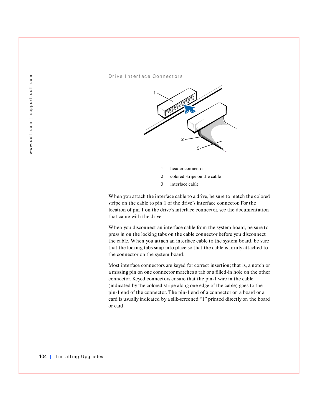
104 Installing Upgrades
Installing Upgrades 105
Hard Drives
106 Installing Upgrades
Installing Upgrades 107
Detaching Hard Drive Cables
108 Installing Upgrades
Installing Upgrades 109
110 Installing Upgrades
Removing a Hard Drive
Installing Upgrades 111
Installing a Hard Drive
112 Installing Upgrades
Installing Upgrades 113
Reattaching Hard Drive Cables
114 Installing Upgrades
Installing Upgrades 115
116 Installing Upgrades
Installing Upgrades 117
Floppy Drives
118 Installing Upgrades
Detaching Floppy Drive Cables
Installing Upgrades 119
120 Installing Upgrades
Installing Upgrades 121
122 Installing Upgrades
Removing a Floppy Drive
Installing Upgrades 123
Slide the drive upward and remove it from the computer
Installing a Floppy Drive and Reattaching Cables
124 Installing Upgrades
Small Form-Factor Computer
Installing Upgrades 125
Small Desktop and Small Mini-Tower Computers
126 Installing Upgrades
Installing Upgrades 127
128 Installing Upgrades
CD/DVD Drives
Installing Upgrades 129
Detaching CD, CD-RW, or DVD Drive Cables
130 Installing Upgrades
Installing Upgrades 131
132 Installing Upgrades
Removing a CD, CD-RW, or DVD Drive
Installing Upgrades 133
Installing a CD, CD-RW, or DVD Drive and Reattaching Cables
134 Installing Upgrades
Connect the drive, power, and audio cables to the drive
Installing Upgrades 135
136 Installing Upgrades
Installing Upgrades 137
Battery
138 Installing Upgrades
Replacing the Battery
Installing Upgrades 139
140 Installing Upgrades
Installing Upgrades 141
Installing Upgrades
A n d
Removing the Computer Stand
144 Stand
Attaching the Computer Stand
Stand 145
Stand
Technical Specifications
148 Technical Specifications
Memory
Computer Information
Technical Specifications 149
Audio
Expansion Bus
150 Technical Specifications
Drives
Ports
Sequence option
Technical Specifications 151
Key Combinations
Controls and Lights
Power
152 Technical Specifications
Physical
Technical Specifications 153
Environmental
Solving Problems
Finding Solutions
156 Solving Problems
Using the Dell OptiPlex ResourceCD
Solving Problems 157
Drivers for Your Computer
Power Problems
Video and Monitor Problems
158 Solving Problems
Solving Problems 159
Sound and Speaker Problems
160 Solving Problems
Printer Problems
Solving Problems 161
Serial or Parallel Device Problems
162 Solving Problems
Solving Problems 163
Mouse Problems
164 Solving Problems
Keyboard Problems
Solving Problems 165
Floppy Drive Problems
166 Solving Problems
Solving Problems 167
Hard Drive Problems
168 Solving Problems
Solving Problems 169
170 Solving Problems
Battery Problems
Solving Problems 171
Expansion Card Problems
172 Solving Problems
Recover From a Program That Is Not Responding
Solving Problems 173
Repairing a Wet Computer
174 Solving Problems
Restart a Computer That Is Not Responding
Repairing a Dropped or Damaged Computer
Solving Problems 175
Computer Memory Problems
176 Solving Problems
Hardware Conflicts
System Board Problems
Solving Problems 177
178 Solving Problems
When to Use the Dell Diagnostics
Dell Diagnostics
Resetting a Damaged System Board
Features
Before You Start Testing
Running the Dell Diagnostics
180 Solving Problems
Select Option 1- Dell Diagnostics
Solving Problems 181
Advanced Testing
182 Solving Problems
Solving Problems 183
184 Solving Problems
Advanced Testing Help Menu
Advanced Testing screen
Messages and Codes
Solving Problems 185
Computer Messages
Message Cause Action
Dell Diagnostics
186 Solving Problems
Enter system setup
Solving Problems 187
188 Solving Problems
Getting Help for
Solving Problems 189
Run the System Board
190 Solving Problems
System setup and change
Solving Problems 191
192 Solving Problems
Computer Beep Codes
Code Cause Action
Solving Problems 193
194 Solving Problems
Power Light Code Cause Action
Diagnostics Messages
Diagnostic Lights
Solving Problems 195
196 Solving Problems
Back Panel Lights
Light Problem Description Suggested Resolution Pattern
Solving Problems 197
Software Problems
198 Solving Problems
Solving Problems 199
Operating System Compatibility
200 Solving Problems
Input Errors
Error Messages
Device Drivers
Memory Address Conflicts
Solving Problems 201
Program Conflicts
Interrupt Assignment Conflicts
202 Solving Problems
Used/Available
Line
Getting Help
Help Tools
Help Overview
Technical Assistance
204 Getting Help
World Wide Web
Getting Help 205
Technical Support Service
AutoTech Service
TechFax Service
Automated Order-Status System
Problems With Your Order
Getting Help 207
Before You Call
208 Getting Help
Diagnostics Checklist
Getting Help 209
Australia Sydney
Dell Contact Numbers
Antigua and Barbuda
Austria Vienna
Bermuda
Barbados
Belgium Brussels
Brazil
China Xiamen
Cayman Islands
Chile Santiago
Colombia
El Salvador
Denmark Horsholm
Dominican Republic
Finland Helsinki
Website http//support.euro.dell.com Germany Langen
Home and Small Business
Website http//support.euro.dell.com Corporate
Guatemala
Italy Milan Home and Small Business
Hong Kong
Ireland Cherrywood
Website http//support.euro.dell.com Jamaica
Japan Kawasaki
Website http//support.jp.dell.com Korea Seoul
216 Getting Help
Macau
Latin America
Luxembourg
Malaysia Penang
Netherlands Amsterdam
Mexico
Netherlands Antilles
New Zealand
Peru
Norway Lysaker
Panama
Poland Warsaw
South Africa Johannesburg
St. Lucia
Singapore Singapore
09/091
Taiwan
Sweden Upplands Vasby
Switzerland Geneva
Getting Help 221
Bracknell
Thailand
Trinidad/Tobago
222 Getting Help
A. Austin, Texas
223
US Virgin Islands
Venezuela
224 Getting Help
Additional Information
Regulatory Notices
226 Additional Information
FCC Notices U.S. Only
Additional Information 227
Class a Class B
228 Additional Information
IC Notice Canada Only
CE Notice European Union
Additional Information 229
Battery Disposal
230 Additional Information
EN 55022 Compliance Czech Republic Only
Vcci Notice Japan Only
Additional Information 231
Class a ITE
Class B ITE
232 Additional Information
MIC Notice Republic of Korea Only
Class a Device
Additional Information 233
Polish Center for Testing and Certification Notice
Class B Device
234 Additional Information
Wymagania Polskiego Centrum Badañ i Certyfikacji
Pozosta³e instrukcje bezpieczeñstwa
Additional Information 235
236 Additional Information
Bsmi Notice Taiwan Only
Additional Information 237
Avenida Soles No
NOM Information Mexico Only
México S. de R.I
Col. Peñon de los Baños
DHM-3.0/1.5 a
Información para NOM únicamente para México
Input current rating DHS-2.0/1.0 a
Embarcar a Dell Computer de México
Energy Star Compliance
240 Additional Information
Warranty and Return Policy
Additional Information 241
Additional Information
C r o s o f t Windows XP Features
244 Microsof t Windows XP Features
Overview
Help and Support Center
Switching to Classic View
Microsof t Windows XP Features 245
New User Interface
Clean Desktop Wizard
246 Microsof t Windows XP Features
Notification Area Cleanup
Microsof t Windows XP Features 247
Taskbar Grouping
Files and Settings Transfer Wizard
248 Microsof t Windows XP Features
Microsof t Windows XP Features 249
Application and Device Compatibility
Program Compatibility Wizard
System Restore
250 Microsof t Windows XP Features
Event-Triggered Restore Points
Using System Restore
Scheduled Automatic Restore Points
Microsof t Windows XP Features 251
Restore Process
Manual Restore Points
252 Microsof t Windows XP Features
Microsof t Windows XP Features 253
Driver Rollback
User Accounts and Fast User Switching
How to Use Fast User Switching
254 Microsof t Windows XP Features
What Happens When a Fast User Switch Occurs?
Special Considerations With Fast User Switching
Microsof t Windows XP Features 255
How to Turn Off Fast User Switching
How to Add Users
256 Microsof t Windows XP Features
Network Setup Wizard
Microsof t Windows XP Features 257
Home and Small Office Networking
258 Microsof t Windows XP Features
Internet Connection Firewall
Microsof t Windows XP Features 259
Microsof t Windows XP Features
AGP
Accelerator
Acpi
Ansi
Apic
Bios
API
Ascii
BTU
CIM
CD-R
CD-RW
Cmos
COO
CPU
Crimm
DAT
DCE
Dimm
DMI
DIN
DMA
Dmtf
ECP
DVD
ECC
EDO
ESD
EPP/ECP
Eprom
FCC
FSB
FTP
GUI
Http
Hot-Swappable
Html
Address
IPX/SPX
IDE
IPX
IRQ
LBA
LED
LIF
LVD
MBA
MIF
Mtbf
NIC
Nvram
PET
PBX
PCI
PGA
PIO
PME
Post
RAM
PXE
RAID
Rambus
RTC
Rimm
ROM
Rtcrst
Sdram
Smbios
Scsi
Simm
SPX
Snmp
Spga
Sram
TSR
Tapi
TCP/IP
Udma
UTP
URL
USB
VAC
WOL
Wbem
WfM
WOR
286