1. Introduction
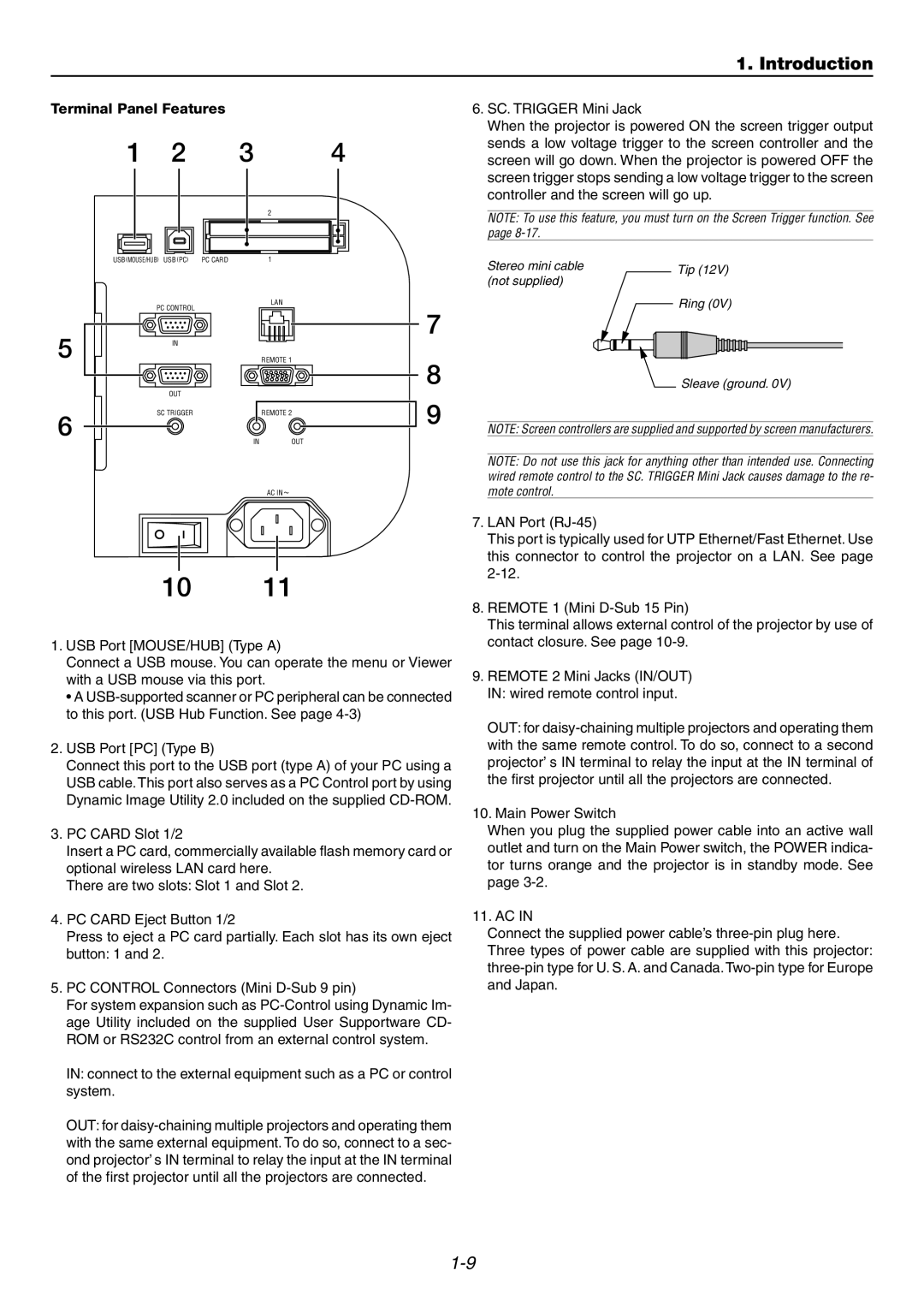
Terminal Panel Features |
| ||
1 | 2 | 3 | 4 |
|
|
| 2 |
USB (MOUSE/HUB) USB (PC) | PC CARD | 1 | |
| PC CONTROL |
| LAN |
|
|
| |
5 | IN |
|
|
|
| REMOTE 1 | |
| OUT |
|
|
6 | SC TRIGGER |
| REMOTE 2 |
| IN | OUT | |
|
| ||
AC IN![]()
7
8
9
6.SC. TRIGGER Mini Jack
When the projector is powered ON the screen trigger output sends a low voltage trigger to the screen controller and the screen will go down. When the projector is powered OFF the screen trigger stops sending a low voltage trigger to the screen controller and the screen will go up.
NOTE: To use this feature, you must turn on the Screen Trigger function. See page
Stereo mini cable |
|
| Tip (12V) | |||
(not supplied) |
|
| ||||
|
|
|
|
| ||
|
|
|
| Ring (0V) | ||
|
|
|
|
|
|
|
|
|
|
|
|
|
|
|
|
|
|
|
|
|
|
|
|
|
|
|
|
Sleave (ground. 0V)
NOTE: Screen controllers are supplied and supported by screen manufacturers.
NOTE: Do not use this jack for anything other than intended use. Connecting wired remote control to the SC. TRIGGER Mini Jack causes damage to the re- mote control.
1011
1.USB Port [MOUSE/HUB] (Type A)
Connect a USB mouse. You can operate the menu or Viewer with a USB mouse via this port.
•A
2.USB Port [PC] (Type B)
Connect this port to the USB port (type A) of your PC using a USB cable. This port also serves as a PC Control port by using Dynamic Image Utility 2.0 included on the supplied
3.PC CARD Slot 1/2
Insert a PC card, commercially available flash memory card or optional wireless LAN card here.
There are two slots: Slot 1 and Slot 2.
4.PC CARD Eject Button 1/2
Press to eject a PC card partially. Each slot has its own eject button: 1 and 2.
5.PC CONTROL Connectors (Mini
For system expansion such as
IN: connect to the external equipment such as a PC or control system.
OUT: for
7.LAN Port
This port is typically used for UTP Ethernet/Fast Ethernet. Use this connector to control the projector on a LAN. See page
8.REMOTE 1 (Mini
This terminal allows external control of the projector by use of contact closure. See page
9.REMOTE 2 Mini Jacks (IN/OUT) IN: wired remote control input.
OUT: for
10.Main Power Switch
When you plug the supplied power cable into an active wall outlet and turn on the Main Power switch, the POWER indica- tor turns orange and the projector is in standby mode. See page
11. AC IN
Connect the supplied power cable’s
