UM581127000 | User Instructions |
| |
Issue AB, March 22, 2012 | Spec. No. 581127000 (Model 710NPBA) |
| |
|
|
|
|
|
|
|
|
Procedure
1)Unpack the module.
2)Note the model number located on the handle of the module. Model numbers starting with the letter “R”
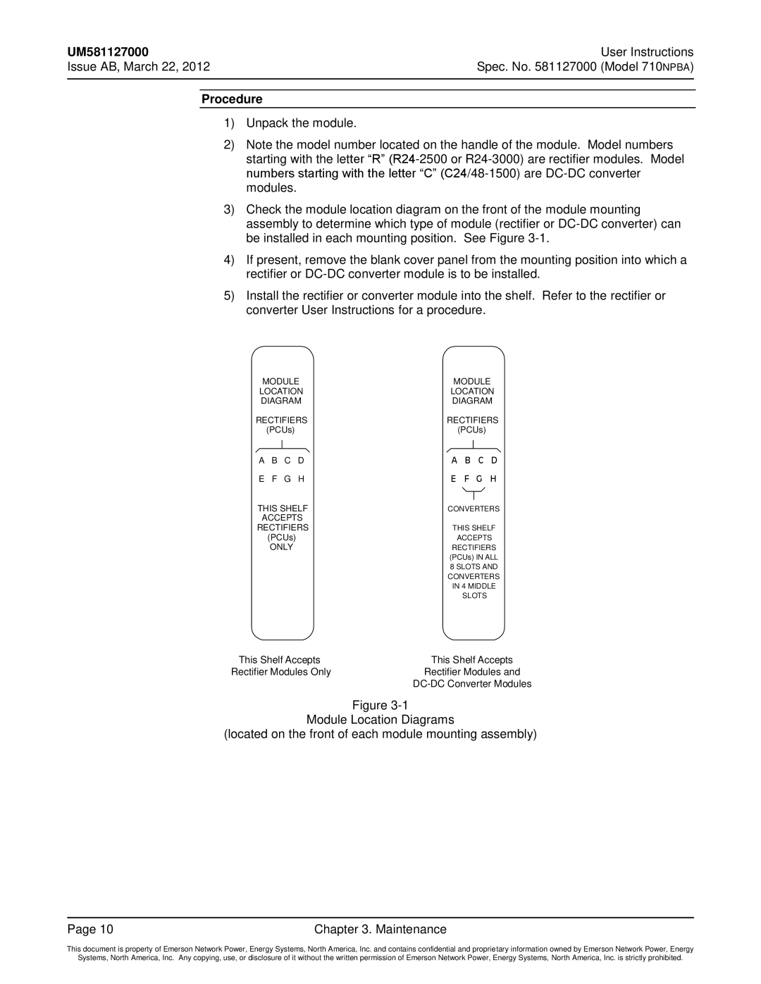
3)Check the module location diagram on the front of the module mounting assembly to determine which type of module (rectifier or
4)If present, remove the blank cover panel from the mounting position into which a rectifier or
5)Install the rectifier or converter module into the shelf. Refer to the rectifier or converter User Instructions for a procedure.
MODULE | MODULE | ||||||||
LOCATION | LOCATION | ||||||||
DIAGRAM | DIAGRAM | ||||||||
RECTIFIERS | RECTIFIERS | ||||||||
| (PCUs) |
|
| (PCUs) |
| ||||
A | B |
| C | D | A | B |
| C | D |
|
| ||||||||
|
| ||||||||
E | F |
| G | H | E | F |
| G | H |
THIS SHELF |
| ||||||||
|
| ||||||||
CONVERTERS | |||||||||
ACCEPTS |
|
|
|
|
| ||||
RECTIFIERS | THIS SHELF | ||||||||
| (PCUs) |
| ACCEPTS | ||||||
| ONLY |
| RECTIFIERS | ||||||
|
|
|
|
| (PCUs) IN ALL | ||||
|
|
|
|
| 8 SLOTS AND | ||||
CONVERTERS
IN 4 MIDDLE
SLOTS
This Shelf Accepts | This Shelf Accepts |
Rectifier Modules Only | Rectifier Modules and |
|
Figure
Module Location Diagrams
(located on the front of each module mounting assembly)
Page 10 | Chapter 3. Maintenance |
This document is property of Emerson Network Power, Energy Systems, North America, Inc. and contains confidential and proprietary information owned by Emerson Network Power, Energy
Systems, North America, Inc. Any copying, use, or disclosure of it without the written permission of Emerson Network Power, Energy Systems, North America, Inc. is strictly prohibited.