UM581127000
Issue AB, March 22, 2012
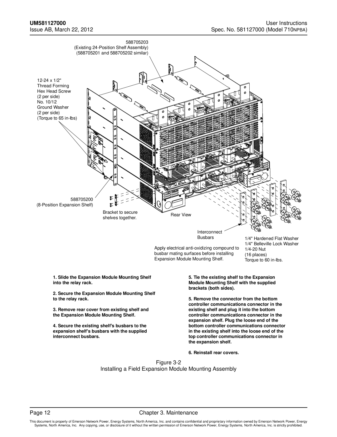
588705203 (Existing
(588705201 and 588705202 similar)
No. 10/12 Ground Washer (2 per side)
(Torque to 65
588705200
User Instructions Spec. No. 581127000 (Model 710NPBA)
Bracket to secure shelves together.
Rear View
Interconnect
Busbars
Apply electrical
1/4" Hardened Flat Washer 1/4" Belleville Lock Washer
(16 places)
Torque to 60
1.Slide the Expansion Module Mounting Shelf into the relay rack.
2.Secure the Expansion Module Mounting Shelf to the relay rack.
3.Remove rear cover from existing shelf and the Expansion Module Mounting Shelf.
4.Secure the existing shelf’s busbars to the expansion shelf’s busbars with the supplied interconnect busbars.
5.Tie the existing shelf to the Expansion Module Mounting Shelf with the supplied brackets (both sides).
5.Remove the connector from the bottom controller communications connector in the existing shelf and plug it into the bottom controller communications connector in the expansion shelf. Plug the loose end of the bottom controller communications connector in the existing shelf into the loose end of the top controller communications connector in the expansion shelf.
6.Reinstall rear covers.
Figure
Installing a Field Expansion Module Mounting Assembly
Page 12 | Chapter 3. Maintenance |
This document is property of Emerson Network Power, Energy Systems, North America, Inc. and contains confidential and proprietary information owned by Emerson Network Power, Energy
Systems, North America, Inc. Any copying, use, or disclosure of it without the written permission of Emerson Network Power, Energy Systems, North America, Inc. is strictly prohibited.