User Instructions | UM581127000 |
Spec. No. 581127000 (Model 710NPBA) | Issue AB, March 22, 2012 |
|
|
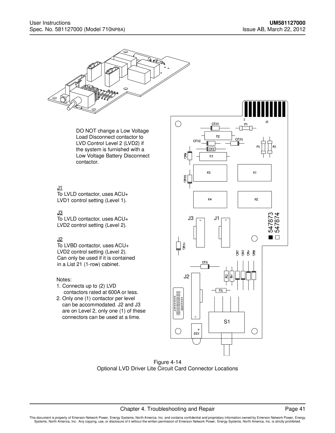
DO NOT change a Low Voltage Load Disconnect contactor to LVD Control Level 2 (LVD2) if the system is furnished with a Low Voltage Battery Disconnect contactor.
J1
To LVLD contactor, uses ACU+ LVD1 control setting (Level 1).
J3
To LVLD contactor, uses ACU+ LVD2 control setting (Level 2).
J2
To LVBD contactor, uses ACU+ LVD2 control setting (Level 2). Can only be used if it is contained in a List 21
Notes:
1.Connects up to (2) LVD contactors rated at 600A or less.
2.Only one (1) contactor per level can be accommodated. J2 and J3 are on Level 2, only one (1) of these connectors can be used at a time.
J3 | J1 |
J2 |
|
| S1 |
Figure
Optional LVD Driver Lite Circuit Card Connector Locations
Chapter 4. Troubleshooting and Repair | Page 41 |
This document is property of Emerson Network Power, Energy Systems, North America, Inc. and contains confidential and proprietary information owned by Emerson Network Power, Energy
Systems, North America, Inc. Any copying, use, or disclosure of it without the written permission of Emerson Network Power, Energy Systems, North America, Inc. is strictly prohibited.