UM581127000 | User Instructions | ||
Issue AB, March 22, 2012 | Spec. No. 581127000 (Model 710NPBA) | ||
|
|
|
|
|
|
|
|
| Replacing a TPS/TLS Fuse |
|
|
|
|
|
|
| Procedure |
|
|
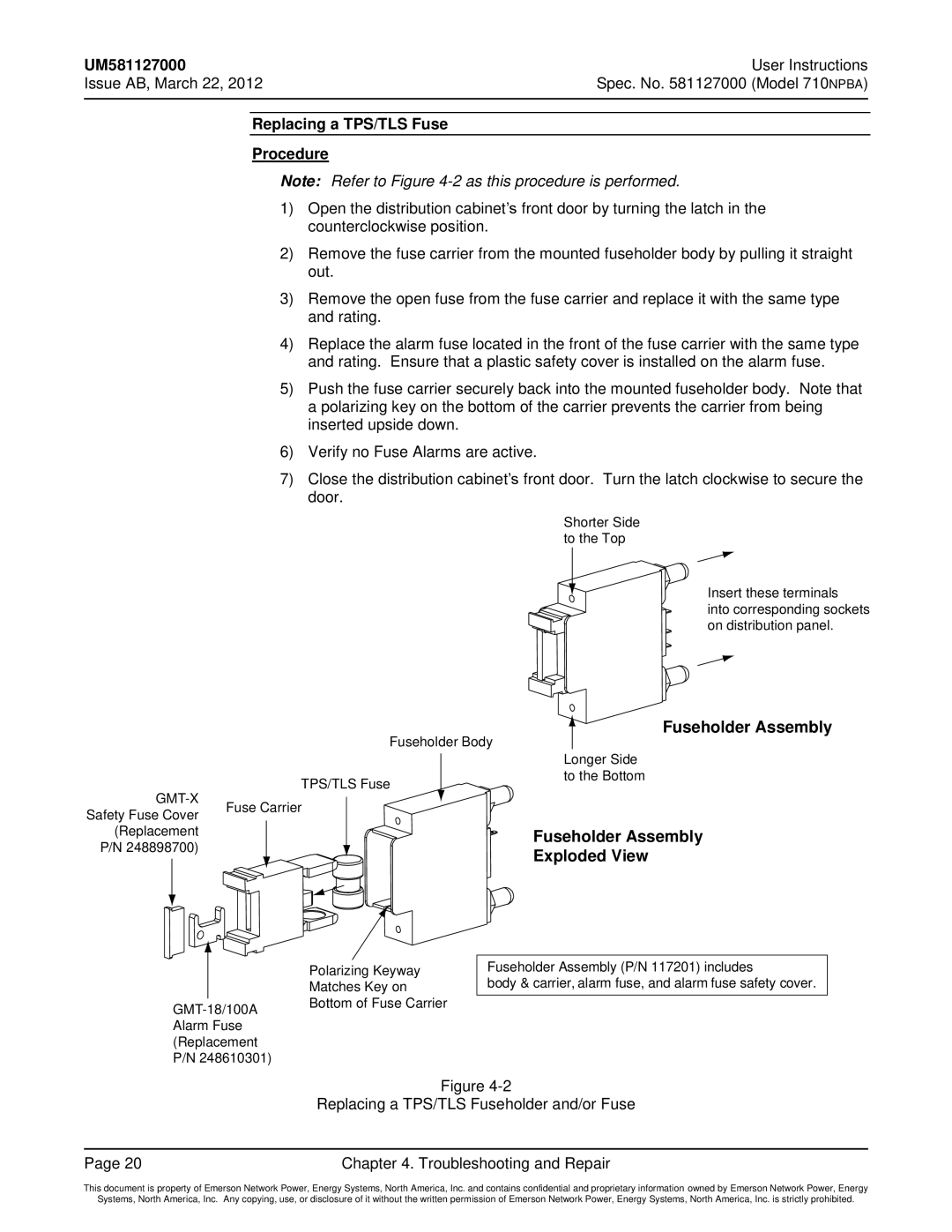
Note: Refer to Figure
1)Open the distribution cabinet’s front door by turning the latch in the counterclockwise position.
2)Remove the fuse carrier from the mounted fuseholder body by pulling it straight out.
3)Remove the open fuse from the fuse carrier and replace it with the same type and rating.
4)Replace the alarm fuse located in the front of the fuse carrier with the same type and rating. Ensure that a plastic safety cover is installed on the alarm fuse.
5)Push the fuse carrier securely back into the mounted fuseholder body. Note that a polarizing key on the bottom of the carrier prevents the carrier from being inserted upside down.
6)Verify no Fuse Alarms are active.
7)Close the distribution cabinet’s front door. Turn the latch clockwise to secure the door.
Shorter Side to the Top
Insert these terminals
into corresponding sockets on distribution panel.
Fuseholder Assembly
Fuseholder Body
|
| Longer Side |
| TPS/TLS Fuse | to the Bottom |
| ||
Fuse Carrier |
| |
Safety Fuse Cover |
| |
|
| |
(Replacement |
| Fuseholder Assembly |
P/N 248898700) |
| |
| Exploded View | |
|
|
Polarizing Keyway Matches Key on Bottom of Fuse Carrier
Fuseholder Assembly (P/N 117201) includes
body & carrier, alarm fuse, and alarm fuse safety cover.
Figure
Replacing a TPS/TLS Fuseholder and/or Fuse
Page 20 | Chapter 4. Troubleshooting and Repair |
This document is property of Emerson Network Power, Energy Systems, North America, Inc. and contains confidential and proprietary information owned by Emerson Network Power, Energy
Systems, North America, Inc. Any copying, use, or disclosure of it without the written permission of Emerson Network Power, Energy Systems, North America, Inc. is strictly prohibited.